


www.desatech.com
111076-01F16
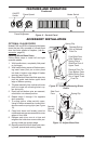
MAINTENANCE
WARNING: Disconnect
power before attempting any
maintenance or cleaning to re-
duce the risk of re, electrical
shock or personal injury.
WARNING: Any electrical
repairs or rewiring of this unit
should be carried out by a li-
censed electrician in accordance
with national and local codes.
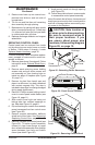
WARNING: Do not exceed
60 watts per bulb when replac-
ing bulbs. Use of higher-rated
bulbs may result in a re, caus-
ing property damage, personal
injury, or loss of life.
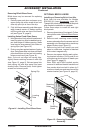
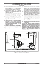
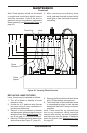
REPLACING LIGHT BULBS
There are (3) colored lamps rated at 120V,
60 Watts, for use in a medium sized socket.
These bulbs are located under the log bed
and can be replaced as follows:
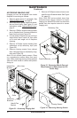
1. If you are unsure which bulb needs re-
placement, defective bulbs may be visually
located as any of 3 bulbs colored - Red,
Yellow and Orange starting from the left
(see Figure 9, page 7). Defective bulbs can
be replaced individually or for convenience
you may want to replace all bulbs at the
same time; even if only one is defective.
2. Disconnect power to unit at main breaker
or fuse panel.
3. Lift log bed off hearth base to gain access
to lamp xtures. Log bed is attached with
contact magnets only.
4. Remove each defective bulb from its
socket and replace with appropriate color
and size bulb.
Note: Be careful not to tear or damage reec-
tive ribbons. If they have come loose, they
can be easily reattached or replaced at the
support brackets. See Replacing Reective
Ribbons, page 21.
5. Return power to circuit and turn main power
switch and lamp power on to check opera-
tion of bulbs before replacing log set.
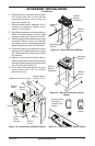
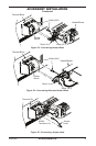
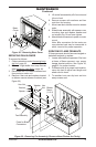
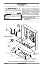
Figure 27 - Removing/Replacing Control
Door
Deector
Shield
Control
Door
Magnet
Assembly
Push
Door Up
and
Back
Angle
Door and
Slide
Out of
Housing.
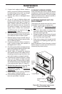
6. If all bulbs are working properly, replace
log bed over center opening between rear
screen and front grate.
CAUTION: Make sure power
is turned off at supply prior to
disassembling this unit.
MAINTAINING MOTORS
Motors used on fan and heater assembly
are permanently lubricated and do not
require lubrication. Annual cleaning and/or
vacuuming around heater and fan unit is
recommended.
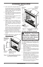
REMOVING/REPLACING CONTROL
DOOR
Upper control door may be removed for ser-
vice or replacement when necessary:
1. Open upper control door (see Figure 10,
page 7).
2. Remove 4 Phillips screws from deector
shield. Angle deector shield out of open-
ing (see Figure 27).
3. Remove 4 Phillips screws from magnet
assemblies.
4. Lift up on inner control door and push
in each end until pivot pins are free of
notches located on each side of access
opening (see Figure 27).