


www.desatech.com
111076-01F6
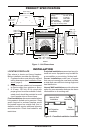
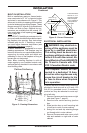
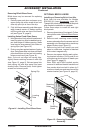
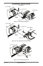
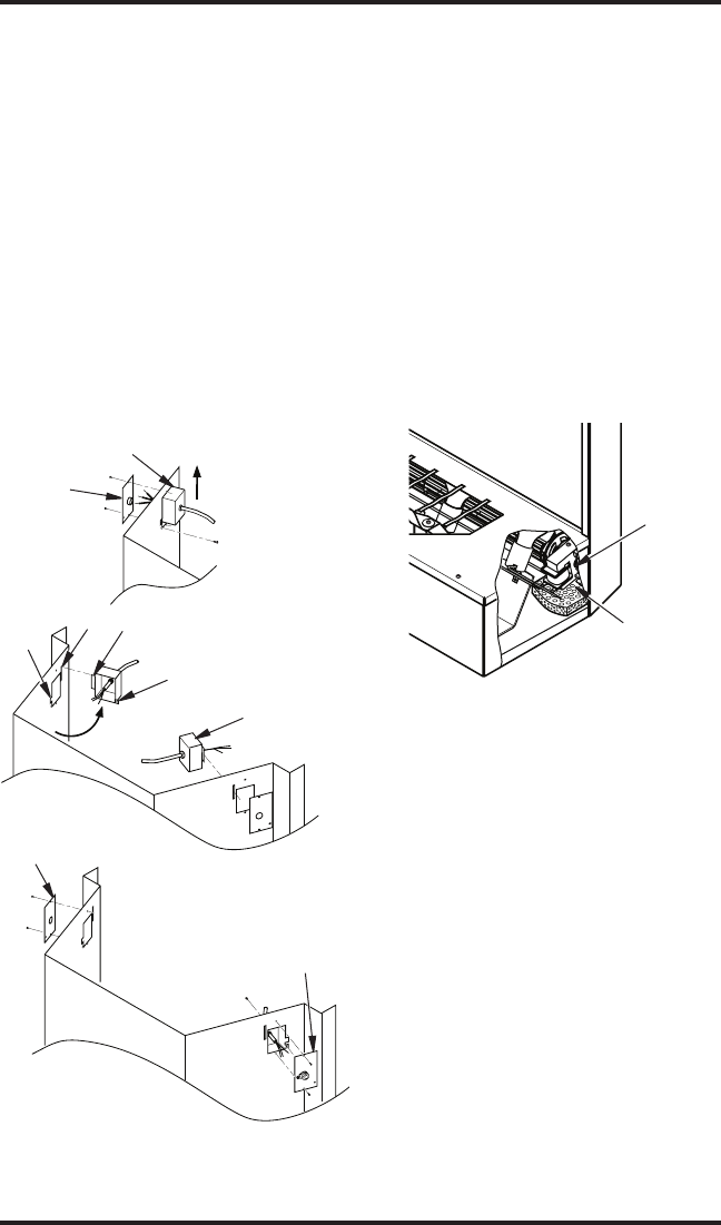
6. Swing junction box with harness to left
side while pulling sufcient length of har-
ness out through control panel cover to
reach mounting location on left side.
7. Reinsert retaining ange through slot and
swing screw mounting tab back through
notch as before.
8. Slide junction box down until mounting
holes line up and replace inner retaining
cover.
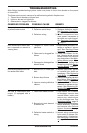
9. Pull end of 3 wire Romex supply line
through universal strain relief bushing in
remaining cover.
10. Strip back outer Romex to about 4” and
connect black, white and green wires ac-
cordingly using approved connectors.
Screws
and
Outer
Cover
Junction Box
Mounting
Tab
Notch
Retaining
Flange
Slot
Screws and
Outer Cover
from Other Side
Cover with
Universal
Strain Relief
Figure 7 - Relocating Junction Box to
Left
INSTALLATION
Continued
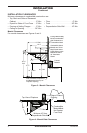
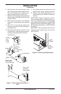
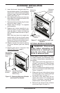
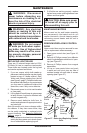
Junction Box
Figure 8 - Removing Shipping Brace
Foam
Shipping
Brace
Motor
Mount
11. Tuck tailing wires into junction box and
replace cover using 2 remaining screws.
12. Tighten down strain adjustment on uni-
versal bushing until Romex sheathing is
secured.
IMPORTANT: Inspect components and wir-
ing for damage before connecting power to
unit. If any components are found damaged,
contact an authorized dealer for original DESA
Heating Products replacement part(s) or call
DESA Heating Products at 1-866-872-6040
for referral.
IMPORTANT: Prior to operation remove foam
shipping brace located under motor mount
(see Figure 8).