


901273-01D
6
For more information, visit www.desatech.com
For more information, visit www.desatech.com
O
F
F
P
I
L
O
T
O
N
INSTALLATION
Continued
INSTALLATION
Checking Gas Connections
Hearth Kit Installation
WARNING: Test all gas piping and connections
for leaks after installing or servicing. Correct all leaks
at once.
WARNING: Never use an open flame to check for
a leak. Apply a noncorrosive leak detection fluid to all
joints. Bubbles forming show a leak. Correct all leaks
at once.
CHECKING GAS CONNECTIONS
Pressure Testing Gas Supply Piping System
Test Pressures In Excess Of 1/2 PSIG (3.5 kPa)
1. Disconnect log set and its individual equipment shutoff valve
from gas supply piping system.
2. Cap off open end of gas pipe where equipment shutoff valve
was connected.
3. Pressurize supply piping system by either using compressed
air or opening main gas valve located on or near gas meter.
4. Check all joints of gas supply piping system. Apply a noncor-
rosive leak detection fluid to all joints. Bubbles forming show
a leak.
5. Correct all leaks at once.
6. Reconnect log set and equipment shutoff valve to gas supply.
Check reconnected fittings for leaks.
Test Pressures Equal To or Less Than 1/2 PSIG (3.5 kPa)
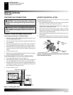
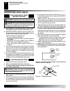
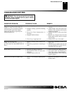
1. Close equipment shutoff valve (see Figure 5).
2. Pressurize supply piping system by either using compressed
air or opening main gas valve located on or near gas meter.
3. Check all joints from gas meter to equipment shutoff valve
(see Figure 5). Apply a noncorrosive leak detection fluid to all
joints. Bubbles forming show a leak.
4. Correct all leaks at once.
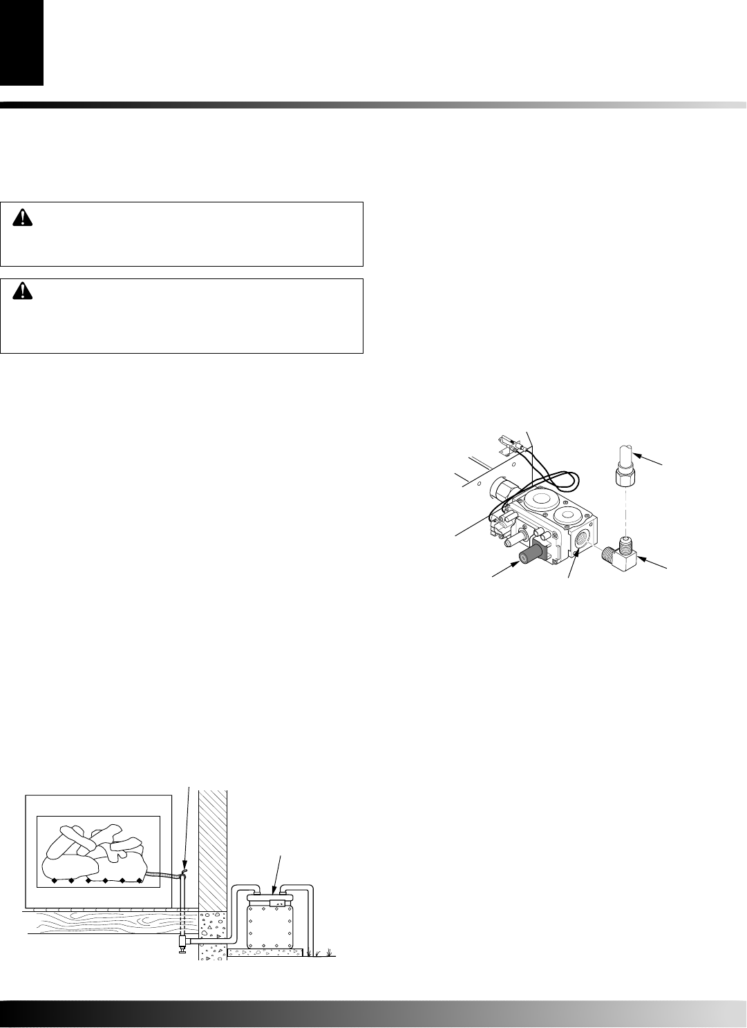
Figure 5 - Checking Gas Joints
Gas Meter
Equipment Shutoff Valve
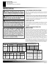
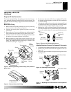
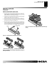
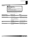
Figure 6 - Installing Inlet Fitting and Gas Connector Tube (Valve
Cover Removed for Clarity)
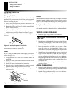
HEARTH PAN INSTALLATION
If using propane/LP gas, see Propane/LP Gas Conversion on page
7, before installing hearth pan.
1. Place the burner pan assembly in the center of the fireplace
floor. Make sure the front of pan faces forward.
2. Thread the gas supply fitting to the fireplace gas supply pipe.
Adjust to most convenient position.
3. Install the gas connector tube to the gas supply adapter. Carefully
shape tube and attach to gas inlet fitting (see Figure 6). Be
careful not to cause kinks in tube.
4. Test for leaks following instructions under Testing Burner for
Leaks, page 8.
5. Retighten and adjust the location of the gas control as necessary.
The gas control should be level, with the control rod to the front.
Gas Control Valve
Gas Inlet
Fitting
Gas
Connector
Tube
Inlet Opening