www.desatech.com
7107883-01H
AIR FOR COMBUSTION
AND VENTILATION
Continued
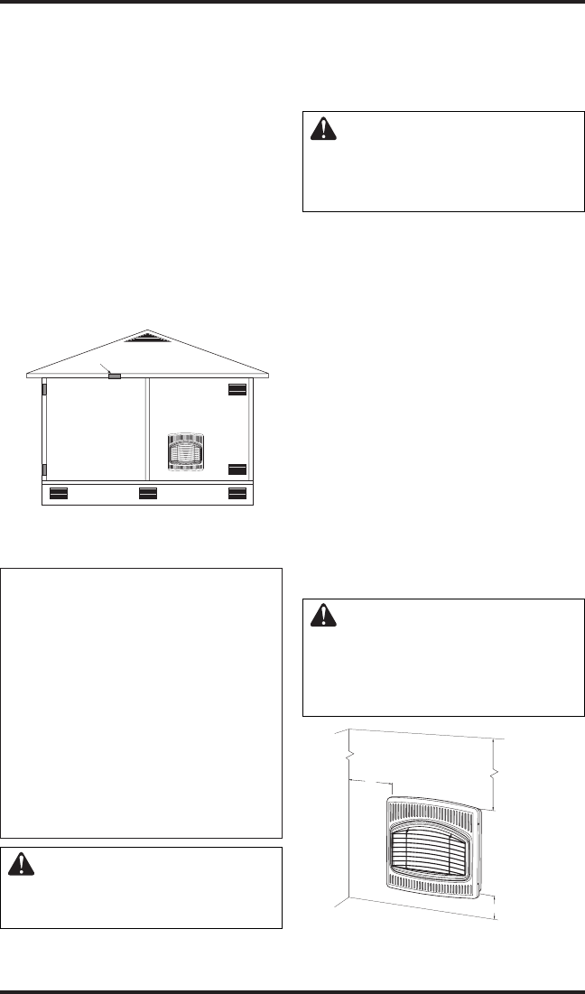
Ventilation Air From Outdoors
Provide extra fresh air by using ventilation grills or
ducts. You must provide two permanent openings:
one within 12” of the ceiling and one within 12”
of the floor. Connect these items directly to the
outdoors or spaces open to the outdoors. These
spaces include attics and crawl spaces. Follow the
National Fuel Gas Code, ANSI Z223.1/NFPA 54,
Section 5.3, Air for Combustion and Ventilation for
required size of ventilation grills or ducts.
IMPORTANT: Do not provide openings for inlet
or outlet air into attic if attic has a thermostat-
controlled power vent. Heated air entering the attic
will activate the power vent.
Figure 3 - Ventilation Air from Outdoors
Outlet
Air
Ventilated
Attic
Outlet
A
ir
Inlet
Air
Inlet Air
Ventilated
Crawl Space
To
Crawl
Space
To Attic
INSTALLATION
NOTICE: This heater is intended
for use as supplemental heat.
Use this heater along with your
primary heating system. Do not
install this heater as your pri
-
mary heat source. If you have a
central heating system, you may
run system’s circulating blower
while using heater. This will help
circulate the heat throughout the
house. In the event of a power
outage, you can use this heater
as your primary heat source.
WARNING: A qualified ser-
vice person must install heater.
Follow all local codes.
CHECK GAS TYPE
Use only the correct type of gas (natural or pro-
pane/LP). If your gas supply is not the correct gas
type, do not install heater. Call dealer where you
bought heater for proper type heater.
WARNING: This appliance
is equipped for (natural or pro
-
pane/LP) gas. Field conversion
is not permitted.
INSTALLATION ITEMS
Before installing heater, make sure you have the
items listed below.
• for propane/LP gas, external regulator (supplied
by installer)
• piping (check local codes)
• sealant (resistant to propane/LP gas)
• equipment shutoff valve *
• ground joint union
• sediment trap
• tee joint
• pipe wrench
• for natural gas, test gauge connection*
* A CSA design-certified equipment shutoff valve
with 1/8" NPT tap is an acceptable alternative to
test gauge connection. The optional CSA design-
certified equipment shutoff valve can be purchased
from your dealer. See
Accessories, page 23.
LOCATING HEATER
WARNING: Maintain the
minimum clearances shown
in Figure 4. If you can, provide
greater clearances from floor,
ceiling and joining wall.
Minimum
From
Sides Of
Heater
36"
2"
FLOOR
CEILING
Minimum
Minimum To
Top Surface
Of Carpeting,
Ti
le Or Other
Combustible
Material
Left
Side
Right
Side
10"
Figure 4 - Mounting Clearances As
Viewed From Front of Heater


