


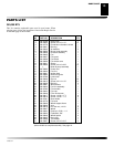
105850-01D
9
9
SERVICE PROCEDURES
SERVICE PROCEDURES
Continued
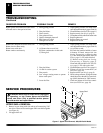
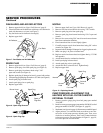
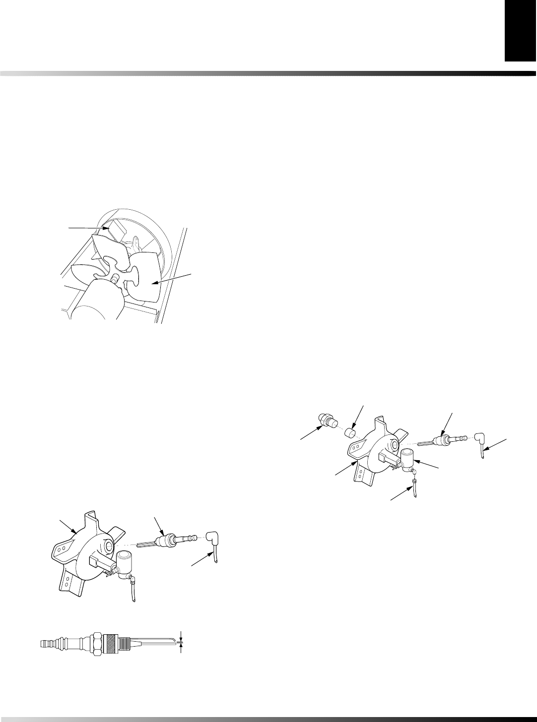
Figure 7 - Fan Blades and Air Deflectors
Fan Blade
Air Deflector
FAN BLADES AND AIR DEFLECTORS
1. Remove upper shell (see Upper Shell Removal, page 8).
2. Clean fan blades and air deflectors with clean, soft cloth moist-
ened with kerosene or solvent (see Figure 7).
3. Dry fan blades and air deflectors thoroughly.
4. Replace upper shell.
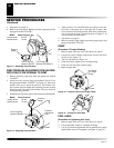
Figure 8 - Spark Plug Removal
Spark
Plug Wire
Spark Plug
Burner Head
.075
inch
Figure 9 - Spark Plug Gap
SPARK PLUG
1. Remove upper shell (see Upper Shell Removal, page 8).
2. Remove spark plug wire from spark plug (see Figure 8).
3. Remove spark plug from burner head using 13/16"
open-end wrench (see Figure 8).
4. Replace spark plug if damaged or heavily coated with carbon.
5. Clean and regap spark plug electrodes to .075 inch (see Figure 9).
6. Install spark plug in burner head.
7. Attach spark plug wire to spark plug.
8. Replace upper shell.
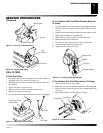
NOZZLE
1. Remove upper shell (see Upper Shell Removal, page 8).
2. Remove fuel line from solenoid valve using 7/16" wrench.
3. Remove spark plug wire from spark plug.
4. Remove spark plug from burner head using 13/16" open-end
wrench.
5. Remove five screws using 5/16" nut-driver and remove burner
head from combustion chamber.
6. Place burner head into vise and lightly tighten.
7. Carefully remove nozzle from burner head using 5/8" socket
wrench (see Figure 10).
8. Inspect nozzle for damage. If damaged or clogged, replace nozzle.
9. Make sure plug is in place on burner head.
10. Replace nozzle into burner head and tighten firmly (175-200
inch-pounds).
11. Attach burner head to combustion chamber.
12. Install spark plug in burner head.
13. Attach spark plug wire to spark plug.
14. Attach fuel line to solenoid valve. Tighten firmly.
15. Replace upper shell.
Figure 10 - Replacing Nozzle
Spark Plug
Burner
Head
Fuel Line
Solenoid
Valve
Plug
Nozzle
Spark
Plug
Wire
PUMP PRESSURE ADJUSTMENT FOR
HEATERS WITH FUEL FILTER/CANISTER
EXTERNAL TO PUMP
1. Remove pressure gauge plug from fuel pump port marked
“GAUGE.”
2. Install accessory pressure gauge (part number 110380-01) to fuel
pump port marked “GAUGE” (see Figure 11, page 10).
3. Start heater (see Operation, page 4). Allow motor to reach full speed.
4. Adjust pressure. Use small flat blade screwdriver to turn slot-
ted screw at fuel pump pressure adjusting port. Turn screw
clockwise to increase pressure. Turn screw counterclockwise
to decrease pressure. See specifications in Figure 11, page 10,
for correct pressure for each model.