


8
103569
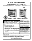
VENT-FREE PROPANE/LP GAS HEATER
BLUE-FLAME CGP20, CGP20L AND RP30D
Continued
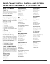
CONNECTING TO
GAS SUPPLY
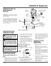
The installer must supply an external regu-
lator. The external regulator will reduce
incoming gas pressure. You must reduce
incoming gas pressure to between 11 and 14
inches of water. If you do not reduce incom-
ing gas pressure, heater regulator damage
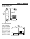
could occur. Install external regulator with
the vent pointing down as shown in Figure
12. Pointing the vent down protects it from
freezing rain or sleet.
NOTICE: A qualified service per-
son must connect heater to gas
supply. Follow all local codes.
CAUTION: Never connect
heater directly to the propane/LP
supply. This heater requires an
external regulator (not supplied).
Install the external regulator be-
tween the heater and propane/LP
supply.
CAUTION: Use only new,
black iron or steel pipe. Inter-
nally-tinned copper tubing may
be used in certain areas. Check
your local codes. Use pipe of 1/2"
diameter or greater to allow
proper gas volume to heater. If
pipe is too small, undue loss of
pressure will occur.
Install sediment trap in supply line as shown
in Figure 13, page 9. Locate sediment trap
where it is within reach for cleaning. Locate
sediment trap where trapped matter is not
likely to freeze. A sediment trap traps mois-
ture and contaminants. This keeps them
from going into heater controls. If sediment
trap is not installed or is installed wrong,
heater may not run properly.
CAUTION: Use pipe joint seal-
ant that is resistant to liquid pe-
troleum (LP) gas.
Installation must include a manual shutoff
valve, union, and plugged 1/8" NPT tap.
Locate NPT tap within reach for test gauge
hook up. NPT tap must be upstream from
heater (see Figure 13, page 9).
Apply pipe joint sealant lightly to male
threads. This will prevent excess sealant
from going into pipe. Excess sealant in pipe
could result in clogged heater valves.
Typical Inlet Pipe Diameters
20,000 Btu/Hr models 3/8" or greater
30,000 Btu/Hr models 1/2" or greater
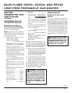
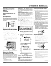
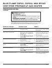
Placing Heater On Mounting
Bracket
1. Locate two horizontal slots on back
panel of heater.
2. Place heater onto mounting bracket.
Slide horizontal slots onto stand-out
tabs on mounting bracket.
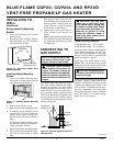
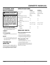
Installing Bottom Mounting
Screws
1. Locate two bottom mounting holes.
These holes are near bottom on back
panel of heater (see Figure 11).
Figure 10 - Mounting Heater Onto
Mounting Bracket
2. Mark screw locations on wall.
3. Remove heater from mounting bracket.
4. If installing bottom mounting screws
into hollow or solid wall, install wall
anchors. Follow steps 1 through 4 un-
der Attaching To Wall Anchor Method,
page 7.
If installing bottom mounting screw
into wall stud, drill holes at marked lo-
cations using 9/64" drill bit.
5. Replace heater onto mounting bracket.
6. Place spacers between bottom mount-
ing holes and wall anchor or drilled
hole.
Figure 11 - Installing Bottom Mounting
Screws
INSTALLING TO
WALL
Continued
Stand-Out Tab
Mounting Bracket
(attached to wall)
Horizontal
Slots
7. Hold spacer in place with one hand.
With other hand, insert mounting screw
through bottom mounting hole and
spacer. Place tip of screw in opening
of wall anchor or drilled hole.
8. Tighten both screws until heater is
firmly secured to wall. Do not over
tighten.
Note:
Do not replace front panel at this
time. Replace front panel after making
gas connections and checking for leaks
(see pages 8-9).
Propane/LP
Supply Tank
Vent
Pointing
Down
External
Regulator
Figure 12 - External Regulator with Vent
Pointing Down