


111245-01A
For more information, visit www.desatech.com
For more information, visit www.desatech.com
20
INSTALLATION
Built-In Fireplace Installation (Cont.)
Assembling And Attaching Optional Brass Trim
INSTALLATION
Continued
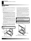
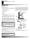
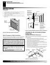
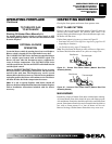
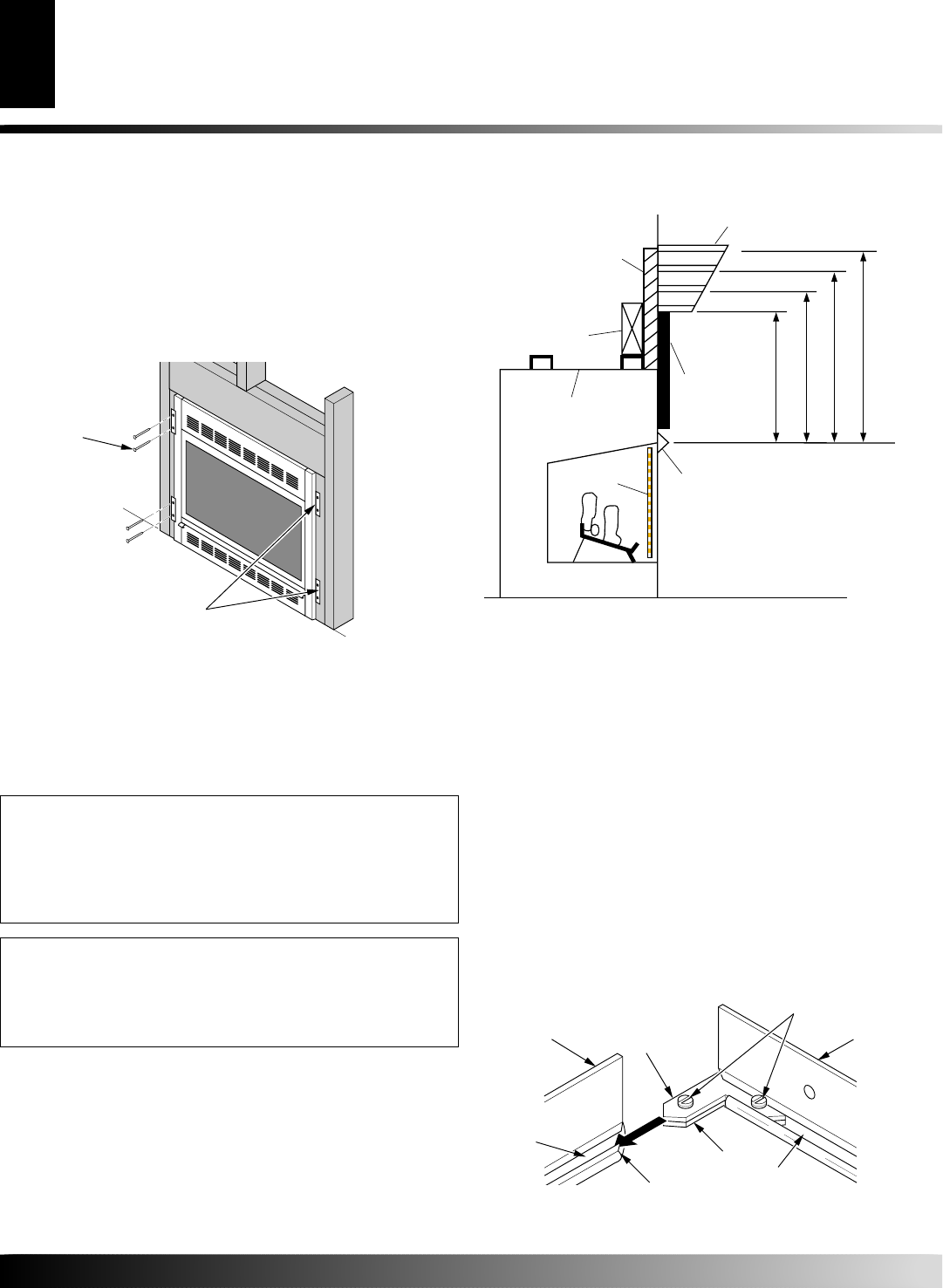
Figure 36 - Attaching Fireplace to Wall Studs
Nailing
Flanges
Nails or
Wood
Screws
8. Attach fireplace to wall studs using nails or wood screws
through holes in nailing flange (see Figure 36).
9. Check all gas connections for leaks. See Checking Gas Con-
nections, pages 17 and 18.
10. Install brass trim. See Assembling and Attaching Optional
Brass Trim.
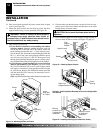
Mantel Clearances for Built-In Installation
If placing mantel above built-in fireplace, you must meet minimum
clearance between mantel shelf and top of fireplace opening.
NOTICE: Surface temperatures of adjacent walls and
mantels become hot during operation. Walls and
mantels above the firebox may become hot to the
touch. If installed properly, these temperatures meet
the requirement of the national product standard.
Follow all minimum clearances shown in this manual.
NOTICE: If your installation does not meet the mini-
mum clearances shown, you must do one of the
following:
• raise the mantel shelf to an acceptable height
• remove the mantel shelf
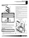
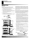
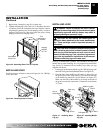
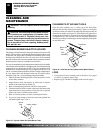
Figure 37 - Minimum Mantel Clearances for Built-In Installation
Supplied Firebox
Hood Must Be
Used at All Times
Wire-mesh
Screen
Firebox
Noncombustible
Material May
Project Off this
Surface above
the Firebox Hood
Mantel Shelf
13" 16" 19" 21"
2
1
/2
"
6"
8"
10"
Note:
All vertical
measurements are
from top of fireplace
hood opening to bottom
of mantel shelf.
These minimum
clearances replace any
other recommended
clearances supplied with
your ANSI Z21.11.2
approved gas logs.
Wall board or facing
material (above
firebox) may be of
combustible material,
including decorative
mantel ornaments or
other similar projec-
tions off of the facing
material.
Framing
Material
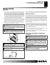
ASSEMBLING AND ATTACHING OPTIONAL
BRASS TRIM
(Included with Mantel Accessory)
Note:
The instructions below show assembling and attaching brass
trim to fireplace.
1. Remove packaging from three pieces of brass trim.
2. Locate four brass screws, two adjusting plates with set screws,
and two shims in the hardware packet.
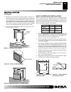
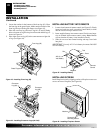
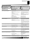
3. Align shim under adjusting plate as shown in Figure 38.
4. Slide one end of adjusting plate/shim in slot on mitered edge
of top brass trim (see Figure 38).
5. Slide other end of adjusting plate/shim in slot on mitered edge
of side brass trim (see Figure 38).
6. While firmly holding edges of brass trim together, tighten both
set screws on the adjusting plate with slotted screwdriver.
Figure 38 - Assembling Brass Trim
Slot
Mitered Edge
Slot
Shim
Set Screws
Adjusting
Plate
Side Brass
Trim
Top Brass
Trim