


www.desatech.com
111916-01F
16
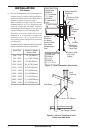
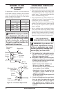
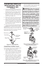
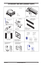
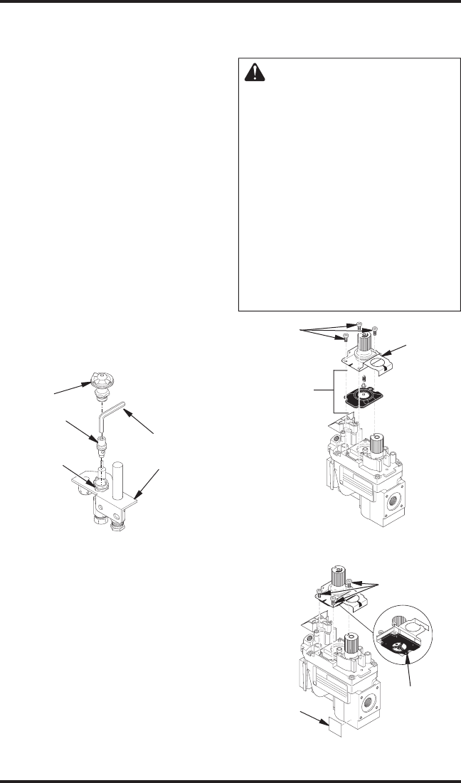
Figure 34 - Converting Pilot
Pilot Hood
Pilot Orifice
Barrel Clip
5/32" Allen
Wrench
Pilot Bracket
6. Locate air shutter at end of burner manifold (end
of tube burner for CD42M series). Loosen screw
and adjust air shutter to proper setting (see Burner
Flame Adjustment, page 13). Retighten screw.
7. Remove pilot hood by pulling up until it
disengages from barrel. Do not remove the
retainer clip (see Figure 34).
8. Remove pilot orifice from inside barrel using
a 5/32" allen wrench to unscrew the orifice.
9. Replace pilot orifice with LP orifice supplied
with this kit. The number 30 is stamped on the
sleeve for identification. Insert small end of
new pilot orifice into barrel and thread until
tight with the allen wrench.
10. Line up notch on pilot hood to the positioning tab
on barrel receiver and snap back into position.
IMPORTANT: Be careful not to bend or kink the
aluminum tubing during conversion. Make sure
the pilot hood and orifice are properly mated and
aligned after finishing this conversion.
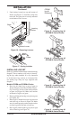
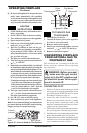
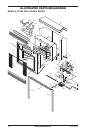
Figure 36- Installing New Parts for Gas
Control Valve Conversion
HI
LO
O
F
F
P
I
L
O
T
O
N
Mounting
Screws
Rubber
Gasket
Identification
Label
3. Install the identification label enclosed with
gas valve regulator to the valve body where
it can easily be seen (see Figure 36).
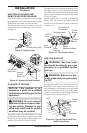
WARNING: The conversion kit
must be installed by a qualified
service technician in accordance
with the manufacturers instruc-
tions and all applicable codes
and requirements of the authority
having jurisdiction. If any informa
-
tion is these instructions is not fol-
lowed correctly, a fire, explosion
or production of carbon monoxide
may result causing property dam-
age, personal injury or loss of life.
The qualified service technician is
responsible for the proper instal-
lation of this conversion kit.
CONVERTING FIREPLACE
FROM NATURAL GAS TO
PROPANE/LP GAS
Continued
CONVERTING CONTROL VALVE
Convert the gas control valve by swapping out the
valve regulator portion of the gas valve.
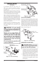
1. Using a TORX T20 or a slotted screwdriver,
remove and discard the three mounting
screws, pressure regulator tower and dia
-
phragm/spring components (see Figure 35).
2. Insure that the rubber gasket is properly
positioned on the new pressure regulator
assembly. Install new pressure regulator as
-
sembly to valve using new mounting screws
supplied with kit. Tighten screws securely
(approximately 25 in/lb). See Figure 36.
HI
LO
O
F
F
P
I
L
O
T
O
N
Figure 35- Removing Parts for Gas
Control Valve Conversion
Diaphragm/
Spring
Components
Mounting
Screws
Pressure
Regulator
Tower