


www.desatech.com
113097-01C
14
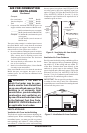
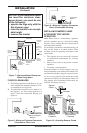
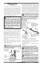
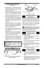
For propane/LP units, the installer must supply
an external regulator. The external regulator will
reduce incoming gas pressure. You must reduce
incoming gas pressure to between 11 and 14 inches
of water. If you do not reduce incoming gas pres
-
sure, heater regulator damage could occur. Install
external regulator with the vent pointing down
as shown in Figure 14. Pointing the vent down
protects it from freezing rain or sleet.
CAUTION: Use only new,
black iron or steel pipe. Inter-
nally-tinned copper tubing may
be used in certain areas. Check
your local codes. Use pipe of
1/2" diameter or greater to allow
proper gas volume to heater. If
pipe is too small, undue loss of
volume will occur.
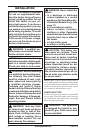
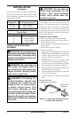
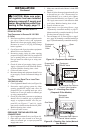
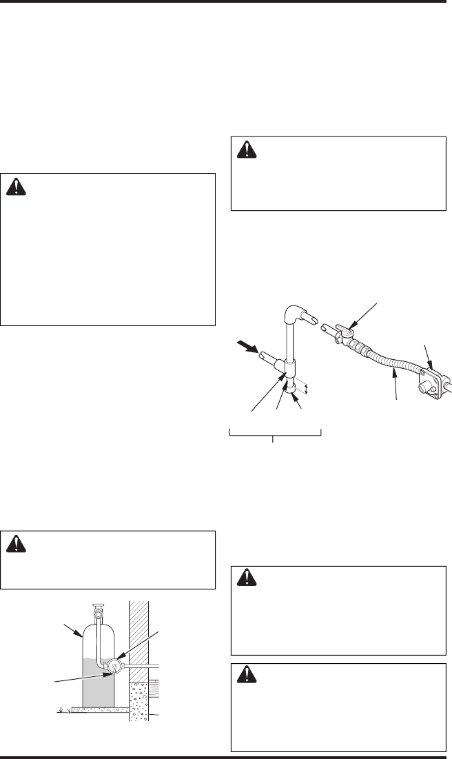
Installation must include an equipment shutoff
valve, union and plugged 1/8" NPT tap. Locate NPT
tap within reach for test gauge hook up. NPT tap
must be upstream from heater (see Figure 15).
IMPORTANT: Install equipment valve in an acces
-
sible location. The equipment shutoff valve is for
turning on or shutting off the gas to the appliance.
Check your building codes for any special re
-
quirements for locating equipment shutoff valve
to fireplaces.
Apply pipe joint sealant lightly to male NPT
threads. This will prevent excess sealant from
going into pipe. Excess sealant in pipe could result
in clogged heater valves.
WARNING: Use pipe joint
sealant that is resistant to liquid
petroleum (LP) gas.
We recommend that you install a sediment trap in
supply line as shown in Figure 15. Locate sediment
trap where it is within reach for cleaning. Install
in piping system between fuel supply and heater.
Locate sediment trap where trapped matter is not
likely to freeze. A sediment trap traps moisture and
contaminants. This keeps them from going into
heater controls. If sediment trap is not installed or
is installed wrong, heater may not run properly.
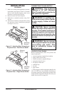
CAUTION: Avoid damage
to regulator. Hold gas regulator
with wrench when connecting it
to gas piping and/or fittings.
INSTALLATION
Continued
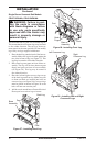
Figure 15 - Gas Connection
* Purchase the optional CSA design-certified
equipment shutoff valve from your dealer. See
Accessories, page 38.
** Minimum inlet pressure for purpose of input
adjustment.
3" Minimum
Sediment Trap
Gas
Regulator
CSA Design-
Certified Equipment
Shutoff Valve With
1/8" NPT Tap*
Approved Flexible
Gas Hose (if allowed
by local codes)
Tee Pipe Cap
Joint Nipple
Figure 14 - External Regulator With Vent
Pointing Down
Propane/LP
Supply Tank
External
Regulator
Vent
Pointing
Down
PROPANE/LP
From External
Regulator (11" W.C.**
to 14" W.C. Pressure)
NATURAL
From Gas Meter
(5" W.C.** to
10.5" W.C.
Pressure)
CHECKING GAS CONNECTIONS
WARNING: Test all gas pip-
ing and connections, internal
and external to unit, for leaks
after installing or servicing. Cor-
rect all leaks at once.
WARNING: Never use an open
flame to check for a leak. Apply a
noncorrosive leak detection fluid
to all joints. Bubbles forming show
a leak. Correct all leaks at once.