


www.desatech.com
117423-01A
6
CHECK GAS TYPE
Use the correct gas type (natural or propane/LP) for
your unit. If your gas supply is not correct, do not
instal in fireplace. Call dealer where you bought
the appliance for proper type of appliance.
WARNING: This appliance
is equipped for (natural or pro-
pane/LP) gas. Field conversion
is not permitted.
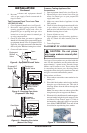
INSTALLATION AND CLEARANCES
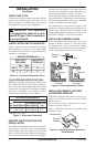
Figure 2 shows technical information regarding
the installation of your gas log set. Please make
sure all specifications shown are applicable before
installation is attempted.
LOG SIZING REQUIREMENTS
MINIMUM FIREBOX SIZE
LOG FRONT REAR* MIN. FLUE
SIZE HEIGHT DEPTH WIDTH WIDTH SIZE
18" 20" 14" 25" 20.5" 6.5"
24" 20" 14" 29" 24.5" 6.5"
*Measured at 14" depth
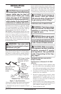
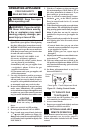
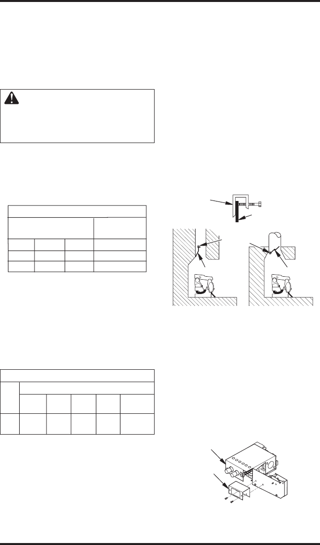
Figure 4 - Attaching Damper Clamp
Manufactured
Fireplace
Masonry
Fireplace
Damper
Damper
Clamp
Damper
Damper
Clamp
Damper
VENTING SPECIFICATIONS FOR
INSTALLATION
The fireplace chimney flue and vent must be draft-
ing properly. To check the vent for proper drafting:
Light a tightly rolled newspaper on one end and
place it at the inside front edge of the fireplace.
Observe the smoke and be sure the vent is properly
INSTALLATION
Continued
SPECIFICATIONS (W.C.)
FUEL INLET MANIFOLD
PRESSURE PRESSURE
Min. Max.
NG 7" 10.5" 3.5"
LP 11" 14" 10"
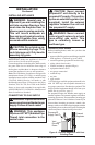
FLUE OPENING SPECIFICATIONS
Note: This vented appliance must be installed only
in a solid-fuel burning or UL127 factory-built fire
-
place constructed of noncombustible material and
connected to a working flue. The fireplace chimney
must have a permanent vent opening to outside
with minimum openings shown in Figure 3.
Figure 2 - Technical Information Chart
Figure 3 - Sizes and Clearances
drawing it up the chimney. If the smoke spills out
into the room, extinguish the flame and remove any
obstruction until proper venting is achieved.
The chimney flue damper must be fixed open to pro
-
vide a minimum of 32 square inch of free air opening
at all times during operation of the log set. A damper
clamp is included to secure the damper.
The minimum flue sizes shown in Figure 3 are
based on a 6' chimney height using round pipe. Your
minimum flue size will vary based on input rate and
chimney height. Refer to the National Fuel Gas Code
ANSI Z223.1/NFPA 54, Section 6.6 for details.
INSTALLING DAMPER CLAMP
Secure the damper stop clam to the edge of the
damper as shown in Figure 4. If for any reason
this clamp doesn't work on your fireplace, another
suitable clamp or permanent stop must be installed,
or the damper blade must be cut or removed.
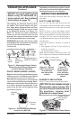
Valve Bracket
INSTALLING REMOTE CONTROL
ACCESSORY BRACKET
If installing optional remote control accessory you
will need to install the remote accessory bracket
for the receiver.
Use screws provided to attach bracket to valve
bracket as shown in Figure 5.
Follow installation instructions included with
remote accessory.
Figure 5 - Attaching Remote Bracket to
Valve Bracket
Remote
Bracket