


103887-01F
8
For more information, visit www.desatech.com
For more information, visit www.desatech.com
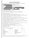
SPECIFICATIONS
Input Rating (Btu/Hr) 150,000
Fuel Natural Gas Only
Fuel Consumption 146 Cubic Feet/Hour
Supply Pressure To Heater Min: 5"WC Max: 1/2 psi
Internal Regulator Outlet Pressure 4" WC (Factory Preset)
Manifold Pressure 4" WC
Hot Air Output (CFM Approx) 550
Motor 3,430 RPM, 1/8 HP
Electric Input 120 V/60 Hz
Amperage 2.2
Ignition Direct Spark, Interrupted Type
Ignitor Gap (Inches) .13/.15
Weight (Pounds)
Heater ............................................. 24
Shipping ......................................... 35
Size - L x W x H (Inches)
Heater ............................................. 32 x 13.5 x 16.5
Carton............................................. 37.5 x 14.25 x 21
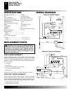
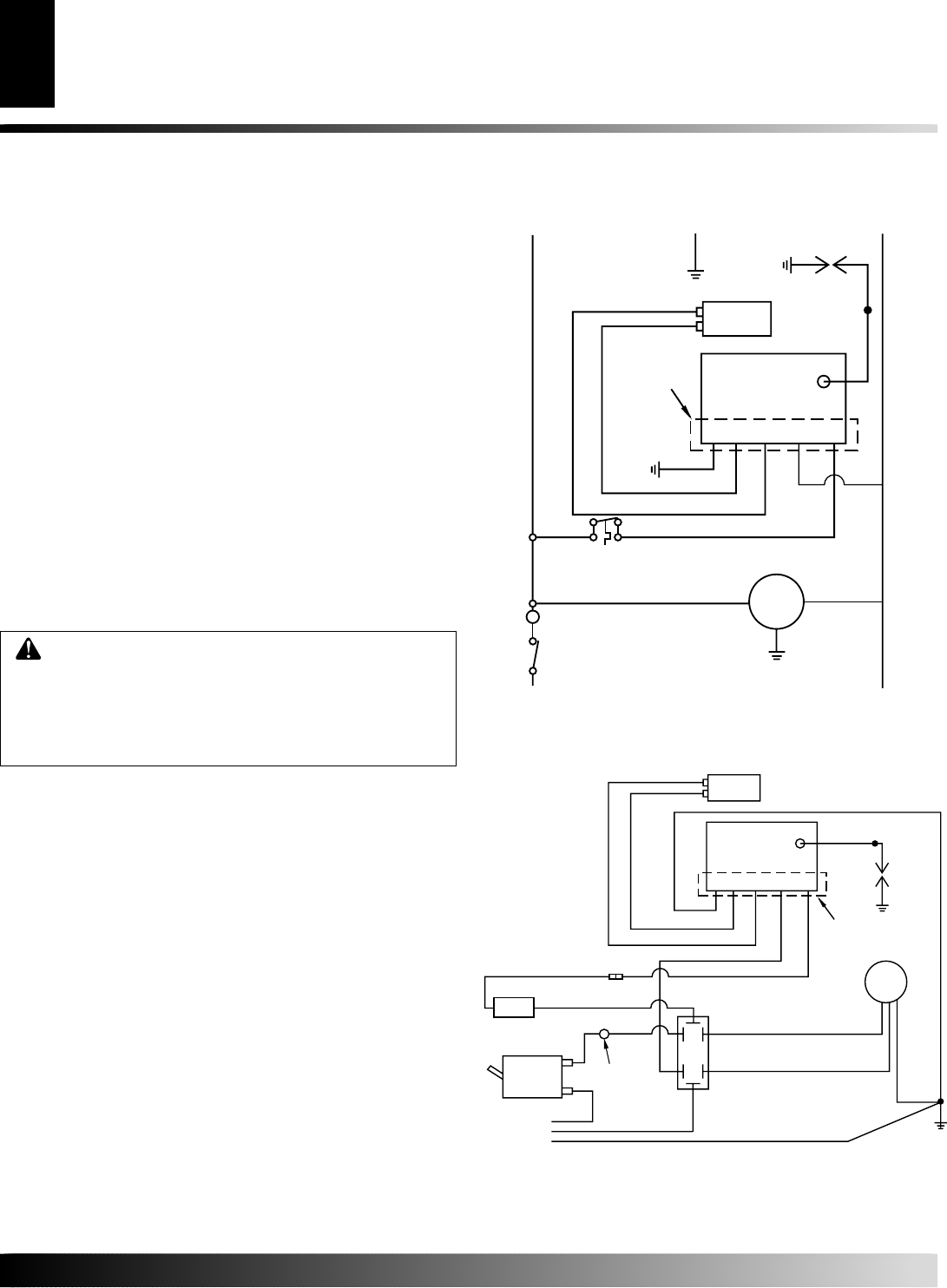
WIRING DIAGRAMS
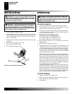
Electrical Connection Diagram
Electrical Ladder Diagram
REPLACEMENT PARTS
PARTS UNDER WARRANTY
Contact authorized dealers of this product. If they can’t supply
original replacement part(s), either contact your nearest Parts
Central or call DESA Heating Products’ Technical Service De-
partment at 1-866-672-6040. When calling DESA Heating Prod-
ucts, have ready:
• your name
• your address
• model and serial numbers of your heater
• how heater was malfunctioning
• purchase date
In most cases, we will ask you to return the part to the factory.
PARTS NOT UNDER WARRANTY
Contact authorized dealers of this product. If they can’t supply
original replacement part(s), either contact your nearest Parts Cen-
tral or call DESA Heating Products at 1-866-672-6040 for referral
information. When calling DESA Heating Products, have ready:
• model number of your heater
• the replacement part number
WARNING: Use only original replacement parts.
This heater must use design-specific parts. Do not
substitute or use generic parts. Improper replace-
ment parts could cause serious or fatal injuries. This
will also protect your warranty coverage for parts
replaced under warranty.
SPECIFICATIONS
REPLACEMENT PARTS
WIRING DIAGRAMS
Line
Neutral
Green or
Green/Yellow
Black
White
Green
Black
White
Motor
Blue
Blue
Blue
Green
Black
White
Orange
Ignitor
Solenoid
Valve
Automatic
Ignition
System
G V VR ACR AC
Position of
Leads May
Vary
T
Orange
Green
Automatic
Ignition
System
G V VR ACR AC
Position of
Leads May
Vary
Blue
Blue
White
White
Black
Blue
Insulated
Connector
Solenoid
Valve
Black
Motor
Power Cord
120 VAC
On/Off
Switch
Black
High Temp
Switch
Black
Thermostat
White
Green
Green
T
Black
Black
Black