


20
105980
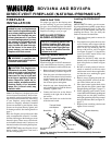
DIRECT-VENT FIREPLACE (NATURAL/PROPANE/LP)
®
BDV34NA AND BDV34PA
FIREPLACE
INSTALLATION
Continued
Test Pressures Equal To or Less Than
1/2 PSIG (3.5 kPa)
1. Close manual shutoff valve (see Fig-
ure 37).
2. Pressurize supply piping system by ei-
ther opening propane/LP supply tank
valve for propane/LP gas fireplace or
opening main gas valve located on or near
gas meter for natural gas fireplace,
or
using compressed air.
3. Check all joints from propane/LP sup-
ply tank or gas meter to manual shutoff
valve (see Figure 38 for propane/LP or
Figure 39 for natural). Apply commer-
cial leak test solution to all gas joints.
Bubbles forming show a leak. Correct
all leaks at once.
Pressure Testing Fireplace Gas
Connections
1. Open manual shutoff valve (see Fig-
ure 37).
2. Open propane/LP supply tank valve for
propane/LP fireplace or main gas valve
located on or near gas meter for natu-
ral gas fireplace.
3. Make sure control knob of fireplace is
in the OFF position.
4. Check all joints from manual shutoff
valve to thermostat gas valve (see Fig-
ure 38 for propane/LP or Figure 39 for
natural). Apply commercial leak test so-
lution to all gas joints. Bubbles forming
show a leak. Correct all leaks at once.
5. Light fireplace (see Operating Fire-
place, pages 24 and 25). Check all other
internal joints for leaks.
6. Turn off fireplace (see To Turn Off Gas
to Appliance, page 24).
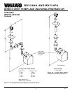
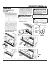
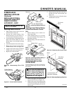
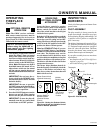
Figure 37 - Manual Shutoff Valve
ON
POSITION
OFF
POSITION
Open
Closed
Manual
Shutoff
Valve
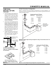
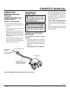
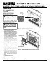
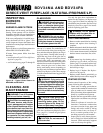
Figure 39 - Checking Gas Joints for Natural Gas Fireplace
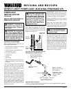
Figure 38 - Checking Gas Joints for Propane/LP Gas Fireplace
Propane/LP Supply
Tank
Gas Valve
Manual
Shutoff Valve
Gas Meter
Gas Valve
Manual
Shutoff Valve
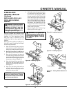
INSTALLING OPTIONAL
WALL MOUNT SWITCH
GWMS2
1. Connect one terminal of 25 ft. wire for
the wall switch to the TPTH terminal
on the valve. Connect remaining wire
terminal to the TH terminal on the
valve. Make sure that the wire termi-
nals are in the positions on the unit as
pictured in Figure 41, page 21. If wires
are not connected as shown the switch
will not work.
2. Route the 25 ft. wire through openings
provided on the sides of the fireplace
to a convenient location to mount your
switch.
3. Connect one bare wire end to each of
the terminals of the GWMS2 wall
switch.
4. Install the wall switch and cover in the
wall.