


www.desatech.com
114144-01B
4
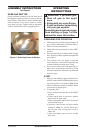
Installation and repair should be
done by a qualified service person.
The heater should be inspected
before use and at least annually by
a qualified service person. More
frequent cleanings may be required
as necessary. It is imperative that
control compartments, burners, and
circulating air passageways of the
heater be kept clean.
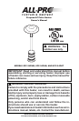
CAUTION: The gas pressure
regulator provided with this ap-
pliance must be used. This regu-
lator is set for an output pressure
of 11" W.C. (2.74 kPa).
PROPANE/LP SAFETY
WARNING: For outdoor
use only.
ASPHYXIATION HAZARD
• Do not use this heater for heating human
living quarters.
• Do not use in unventilated areas.
• The flow of combustion and ventilation
air must not be obstructed.
• Proper ventilation air must be provided
to support the combustion air require
-
ments of the heater being used.
• Refer to the specification section of
the heater’s manual, heater data plate,
or contact DESA Heating Products to
determine combustion air ventilation
requirements of the heater.
• Lack of proper ventilation air will lead
to improper combustion.
• Improper combustion can lead to carbon
monoxide poisoning leading to serious
injury or death. Symptom of carbon mon
-
oxide poisoning can include headaches
dizziness and difficulty in breathing.
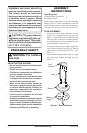
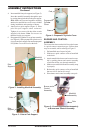
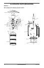
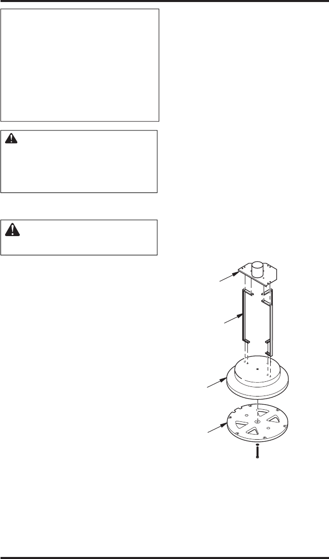
Figure 1 - Base Assembly
Legs
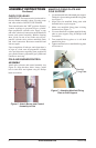
ASSEMBLY
INSTRUCTIONS
Tools Required:
#2 Philips Head Screwdriver 1
Adjustable Wrench 2
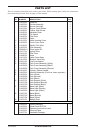
Inspect heater components for possible shipping
damage. If any is found, immediately notify the
dealer. Check to make sure that all components are
included with your heater (see pages 10 and 11).
POLE ASSEMBLY
1. Attach legs to base using large bolts (2), lock
washers (2), and large nuts (2 per leg). See
Figure 1. Insert bolts from through legs and
into top of base. Attach lock washers and nuts
from underneath base. Finger tighten only. Do
not fully tighten until next step.
2. Secure pole support to legs using 6 large bolts,
lock washers and large nuts per leg. Wrench
tighten the nuts and bolts from step 1 (see
Figure 1).
3. Attach ballast weight to base using one, long
bolt, large lock washer and large nut (see
Figure 1).
Base
Pole
Support
Ballast
Weight