


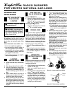

10
901048
FOR VENTED NATURAL GAS LOGS
RADCO BURNERS
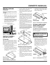
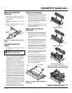
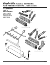
2. Attach the pilot gas line to the pilot out-
let of the gas control valve and tighten.
Connect the thermocouple to the rear of
the gas control valve. See Figure 12. Do
not overtighten. If using propane/LP gas,
see Changing Pilot Orifice, page 11.
3. Install the inlet fitting into the inlet
opening of the gas control valve (see
Figure 13). Use thread sealant on the
male pipe threads.
4. Place the burner pan assembly in the
center of the fireplace floor. Make sure
the front of pan faces forward.
5. Thread the gas supply fitting to the fire-
place gas supply pipe. Adjust to most
convenient position.
6.
Install the gas connector tube to the gas
supply fitting. Carefully shape tube to
attach to adapter fitting.
7. Test for leaks following instructions
under Testing Burner for Leaks, page 11.
8.
Retighten and adjust the location of the
gas control as necessary. The gas con-
trol should be level, with the control rod
to the front.
9. Install cover to burner pan using screws
provided.
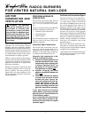
10. Install thermocouple, pilot, and ignitor
onto valve cover as shown in Figure 14.
Use the provided screws.
11. Push the control rod extension onto the
“D” shaped control rod through the cen-
ter hole in the cover.
12.
Install the position decal and control
knob making sure to align the marks
with the correct stop positions of the
gas control. Pilot position will allow the
knob to push in about 1/2". Align the
decals in the pilot position.
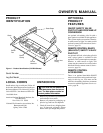
INSTALLATION
Continued
Figure 12 - Gas Control Valve with Ther-
mocouple and Pilot
Figure 13 - Installing Inlet Fitting and Gas
Connector Tube
Piezo Ignitor
Control
Rod
Extension
Screw
Valve Cover
Control
Knob
Figure 14 - Installing Cover, Control Knob,
and Piezo Ignitor
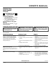
Propane/LP Gas Conversion
To convert to propane/LP gas, the burner
inlet fitting and pilot orifice must be re-
placed. The propane/LP burner inlet fitting is
supplied with the orifice installed for a 24"
log set. If you have an 18" or 30" set, you
must change this orifice also. See Figure 1,
page 3 for product identification.
Burner Inlet Fitting
1. Remove the burner inlet fitting from the
burner pan assembly. DO NOT remove
the orifice from this fitting. The pro-
pane/LP burner inlet fitting is included
in the hardware kit (see Figure 15).
Thermocouple and Line
Pilot and Line
Gas Control Valve
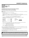
Figure 15 - Burner Inlet Fittings with
Injectors
NATURAL
GAS
FITTING
PROPANE/
LP GAS
FITTING
Injector for
Natural Gas
Injector for
Propane/LP
Gas
Gas Control
Valve
Gas Inlet
Fitting
Gas
Connector
Tube
Figure 16 - Remove Burner Inlet Fitting
Burner Inlet
Fitting for
Natural Gas
Thermocouple
Ignitor
Pilot
Changing Pilot Orifice
The pilot is provided with a natural gas
orifice installed. For propane/LP gas you
must remove it and replace it with an pro-
pane/LP orifice. The hardware kit contains
an propane/LP orifice with a red stripe for
converting the pilot.
1. Gently loosen and remove the pilot
line connection from the bracket (see
Figure 17, page 11).
2. Be sure to use the correct orifice for your
appliance. The hardware kit included
with this appliance contains two orifices
with a cone-like shape. If you have an
18" set, the orifice for the burner inlet
fitting is red; for a 30" set, it is black. If
you have a 24" log set, the orifice is al-
ready installed inside the fitting.
3. For an 18" or 30" set, use a 10mm
socket or nut driver to remove the ori-
fice from the propane/LP burner inlet
fitting. Choose the correct orifice for
your log set size and install in place of
the orifice you just removed.
4. Using thread sealant (resistant to the
action of propane/LP gas) on larger end
of fitting, screw the burner inlet fitting
through hole and into burner manifold.
Tighten using a wrench.
5 . Follow steps 1 through 12 under Natu-
ral Gas Installation, pages 9 and 10.
Inlet
Opening