


4
For more information, visit www.desatech.com
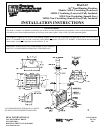
FAN KIT ASSEMBLY: VCBK3E
A Fan Kit is optional (for Models W36C & IW36C only) with
this fireplace. Use of blowers or fans other than manufactured
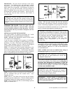
by DESA voids the warranty. Fan is operated by simply
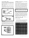
pressing the rocker switch in the lower right corner of the
fireplace face (see figure 6).
NOTE: Fireplace must be wired to the house electrical
system in order for fan to operate. This fan system does not
require a wall switch.
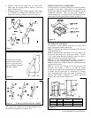
Electrical connections are made through the cover on the side
of the fireplace illustrated in Figure 7. Use 14 AWG copper
wire for all connections. Be certain the fireplace is properly
grounded.
CHIMNEY PIPE
The DESA chimney system consists of 12, 18, 24, 36 and 48
inch, snap-lock double-wall pipe segments, planned for
maximum adaptability to individual site requirements. Actual
lengths gained after fitting overlaps must be taken into
consideration (lineal gain) and are given in the following
chart:
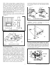
ASSEMBLING AND INSTALLING THE DOUBLE
WALL CHIMNEY SYSTEM
Each double wall chimney section consists of a galvanized
outer pipe, a stainless steel inner flue pipe and a wire spacer.
The pipe sections must be assembled independently as the
chimney is installed. When starting chimney directly to the
fireplace, the inner flue pipe section must be installed first
with the lanced side up. The outer pipe section can then be
installed over the flue pipe section with the hemmed end up.
Press down on each pipe section until the lances securely
engage the hem on the fireplace starter. The wire will assure
the proper spacing between the inner and outer pipe sections.
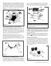
Continue to assemble chimney sections as outlined above,
making sure that both the inner and outer pipe sections are
locked together.
When installing double wall “snap lock”
chimney together, it is important to assure the joint between
the chimney sections is locked. Check by pulling chimney
upward after locking. The chimney will not come apart if
properly locked. It is not necessary to add screws to keep the
chimney together (Exception – see page 5 figure 10).
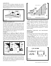
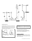
INSTRUCTIONS WHEN ELBOW OFFSET OF
CHIMNEY IS NEEDED: (30E-8DM)
TO INSTALL ELBOWS
1. To achieve desired offset, you may install combinations
of 12”, 18”, 24”, 36” and 48” length of double wall pipe
(SEE SINGLE OFFSET CHART, FIGURE 9 & 11).
OFFSET CHART (22-50 FT. SYSTEM HEIGHT)
Figure 7
Figure 6
O
F
F
O
N
Figure 8
OFFSET RISE
A
B 48" 36" 24" 18" 12"
4 - 3/8 16 -3/8
9 - 3/4 25 - 1/2 1
12 - 3/4 30 - 3/4 1
15 34 - 3/4 1
18 40 1 1
21 - 1/4 46 - 1/4 1
23 - 3/4 49 - 1/4 1 1
27 - 3/4 56 - 3/4 1
30 60 - 3/4 1 1
33 66 1 1
36 71 1 1
38 - 1/4 75 2
41 - 1/4 80 - 1/4 1 1 1
45 86 - 3/4 2
46 - 3/4 89 - 1/2 1 1 1
51 97 1 1
53 - 1/4 101 2 1
56 - 1/4 106 - 1/4 2
59 - 1/4 111 - 1/2 1 1 1
61 - 3/4 115 - 1/2 2 1
64 - 3/4 120 - 3/4 2 1
68 - 1/4 127 1 2
70 130 2 1 1
74 - 1/4 137 - 1/2 1 2 1
76 - 3/4 141 - 1/2 1 2 1
79 - 3/4 146 - 3/4 4
ELBOW SET ONLY
CHIMNEY LENGTH
WARNING: The opening in the collar around the
chimney at the top of the fireplace must not be obstructed.
Never use blown insulation to fill the chimney enclosure.