


www.desatech.com
113973-01C
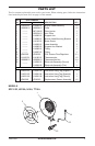
4
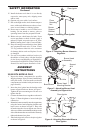
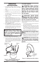
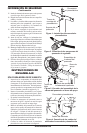
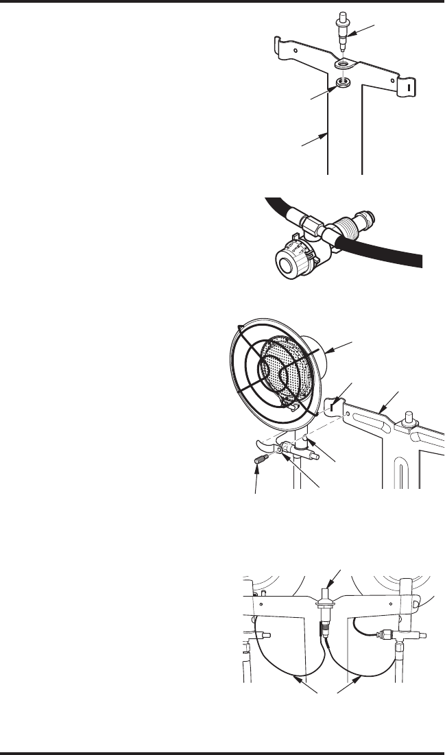
Figure 3 - Attaching Burner Head
Assembly to Support Arm
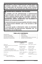
15. Install the heater such that it is not directly
exposed to water spray, rain, dripping water
and/or wind.
16. Operate only on a stable, level surface.
17. Due to the high surface and exhaust tempera
-
tures, adults and children must observe clear
-
ances to avoid burns or clothing ignition.
18. Do not move, handle or service while hot or
burning. Do not attach or remove a hot or
operating heater from the propane/LP tank.
19.
Before each use, check heater for leaks. Never
use an open flame to check for leaks. Apply a
mixture of liquid soap and water to all joints.
Bubbles forming show a leak. Correct all leaks.
20. Keep all connections and fittings clean. Make
sure propane/LP tank valve is clean. Check
"O" ring on heater inlet fuel valve connector
for damage before each use. Replace if worn
or damaged.
21. Use only in accordance with local codes or, in
the absence of local codes, with the Standard
for the Storage and Handling of Liquefied Pe
-
troleum Gases ANSI/NFPA 58 and CSA B149.1,
Natural Gas and Propane Installation Code.
ASSEMBLY
INSTRUCTIONS
30,000 BTU MODELS ONLY
1. Inspect the heater components for possible
shipping damage. If any is found, immediately
notify the dealer. Check to make sure that all
components are included with your heater (see
pages 8 and 9).
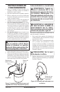
2. Insert the piezo ignitor into the bracket on the
burner support bracket as shown in Figure 1.
Tighten the piezo mounting nut. Do not over
tighten the nut.
3. Connect the burner hoses together as shown in
Figure 2. Wrench tighten to insure leak tight
connection.
4. Mount the burner assembly onto the support arm
using the burner head mounting brackets and
brass screws as shown in Figure 3. Place side
of bracket into the slot on support arm. Secure
with screw. Make certain that the air holes on the
sides of the burner tube are not blocked. Securely
tighten the burners into place.
5. Attach the electrode wires to the piezo ignitor
as shown in Figure 4.
SAFETY INFORMATION
Continued
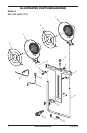
Figure 1 - Installing Piezo Ignitor
Piezo Ignitor
Piezo
Mounting
Nut
Burner
Support
Bracket
Figure 2 - Attaching Burner Hoses to
Regulator
Burner Head
Assembly
Support
Arm
Burner Head
Mounting Bracket
Brass Screw
Slot
Air Hole
Figure 4 - Attaching Electrode Wires to
Piezo Ignitor
Piezo Ignitor
Electrode Wires