


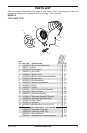
www.desatech.com
118127-01B4
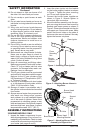
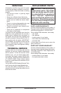
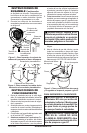
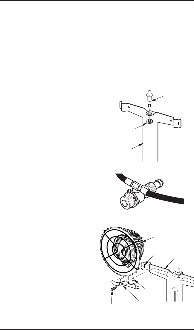
Figure 3 - Attaching Burner Head
Assembly to Support Arm
18. Do not attempt to light one burner off of
the other. Use one match per burner.
19. Do not overlap or point burners at each
other.
20. Do not raise burner heads and cover air
inlet holes in mixing tube with burner head
bracket.
21. Wing nuts and burner heads become
very hot during operation. Do not attempt
to adjust burner position while heater is
operating. Allow 15 minutes to cool.
22. For use with 20 lb. propane cylinders only.
23. Due to the high surface and exhaust
temperatures, adults and children must
observe clearances to avoid burns or
clothing ignition.
24. Do not move, handle or service while hot
or burning. Do not attach or remove a hot
or operating heater from the propane/LP
tank. Severe burns may result.
25. Before each use, check heater for leaks.
Never use an open ame to check for
leaks. Apply a mixture of liquid soap and
water to all joints. Bubbles forming show
a leak. Correct all leaks.
26. Keep all connections and ttings clean.
Make sure propane/LP tank valve is clean.
Check "O" ring on heater inlet fuel valve
connector for damage before each use.
Replace if worn or damaged.
27. The LP gas cylinder must be constructed
and marked in accordance with the speci-
cations for the LP gas cylinders of the
US Department of Transportation (DOT)
or Transport Canada.
28. Use only in accordance with local codes
or, in the absence of local codes, with the
CAN1- B149 Installation Code.
29. Storage of heater is permissible only if
the cylinder is disconnected and removed
from heater.
30. Always remove heater from propane tank
after each use. Always store propane
tank outdoors in a well ventilated space
out of the reach of children. Never store
propane tank in a building, garage, or any
other enclosed area. Never store propane
tank near high heat, open ame, or where
temperatures exceed 100° F (38° C).
ASSEMBLY INSTRUCTIONS
2 BURNER MODELS ONLY
1. Inspect the heater components for pos-
sible shipping damage. If any is found, im-
mediately notify the dealer. Check to make
sure that all components are included with
your heater (see pages 8 and 9).
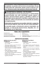
SAFETY INFORMATION
Continued
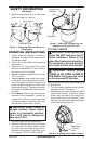
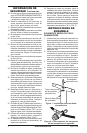
Figure 1 - Installing Piezo Ignitor
Piezo Ignitor
Piezo
Mounting
Nut
Burner
Support
Bracket
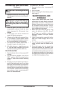
Figure 2 - Attaching Burner Hoses to
Regulator
Burner Head
Assembly
Support
Arm
Burner Head
Mounting Bracket
Brass Screw
Slot
Air Hole
2. Insert the piezo ignitor into the bracket
on the burner support bracket as shown
in Figure 1. Tighten the piezo mounting
nut. Do not over tighten the nut.
3. Connect the burner hoses together as
shown in Figure 2. Wrench tighten to
insure leak tight connection.
4. Mount the burner assembly onto the sup-
port arm using the burner head mounting
brackets and brass screws as shown in
Figure 3. Place side of bracket into the slot
on support arm. Secure with screw. Make
certain that the air holes on the sides of
the burner tube are not blocked. Securely
tighten the burners into place.