


3
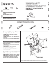
48929 Rev. C
3
A.
B.
D.
1
2
2
E.
1
2
3
C.
3
1
2
F.
3
2
1
4
3
4
5
6
1
4
7
1
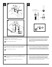
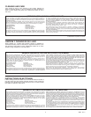
A.
Remove flange (1) and rubber washer (2) from
pop-up body.
B.
Add Teflon
®
tape (1) to the drain body (2).
Insert
threaded end of drain body up through drain
hole and attach flange (3) to body with pivot (4)
pointing to rear of sink.
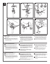
C.
Unscrew the nut (1) from the pop-up body.
Note: retain the seal (2) on the horizontal
rod (3). Place the nut onto the horizontal rod
and insert the rod and seal (2) into the pivot hole
(4). Install stopper (5) as removable (6) or non-
removable (7). Slide nut (1) on and hand tighten.
D.
Tighten nut (1) clockwise until the pop-up
is secure.
Pop-Up Installation
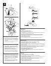
E.
Place one end of spring clip (1) on end of
horizontal rod (2). Insert rod through hole in
lift rod strap (3). Secure with spring clip.
F.
Insert lift rod (1) into strap (2) and tighten
screw (3). Connect assembly to drain (4).
A.
Quite el reborde / brida (1) y la arandela de
goma (2) del cuerpo del desagüe automático.
B.
Aplique la cinta Teflon® (1) al cuerpo del
desagüe (2). Introduzca el extremo enroscado
en el cuerpo del desagüe hacia arriba por el
agujero de drenaje y fije el reborde (3) al cuerpo
con el pivote (4) en dirección hacia la parte de
atrás del lavamanos.
C.
Destornille la tuerca (1) del cuerpo del desagüe
automático. Nota: conserve el sello (2) en la
barra horizontal (3). Coloque la tuerca en la
barra horizontal e introduzca la barra y el sello
(2) en el agujero del pivote (4). Instale el tapón
(5) como desmontable (6) o fijo (7). Deslice la
tuerca (1) y apriete a mano.
D.
Apriete la tuerca (1) en sentido al de las
manecillas del reloj hasta que el desagüe
automático quede fijo.
Instalación del Desagüe Automático
E.
Coloque un extremo del gancho de resorte
(1) en el extremo de la barra horizontal (2).
Introduzca la barra por el agujero de la
barra chata para levantar (3). Fije el gancho
de resorte.
F.
Introduzca la barra de levantar (1) en la
barra chata (2) y apriete el tornillo (3).
Conecte el ensamble al drenaje (4).
A.
Retirez la collerette (1) et la rondelle en
caoutchouc (2) du corps du renvoi.
B.
Appliquez du ruban de Téflon
®
(1) sur le corps
du renvoi (2). Introduisez l’extrémité filetée du
corps du renvoi dans le trou prévu pour le renvoi
et fixez la collerette (3) de manière que le pivot
(4) pointe vers l’arrière de l’évier.
C.
Desserrez l’écrou (1) du corps du renvoi.
Note : Maintenez le joint (2) sur la tige
horizontale (3). Placez l’écrou sur la tige
horizontale, puis introduisez la tige et le joint (2)
dans le trou prévu pour le pivot (4). Installez la
bonde (5) de manière qu’elle soit démontable (6)
ou non démontable (7). Glissez l’écrou (1) sur la
tige et serrez-le à la main.
D.
Serrez l’écrou (1) dans le sens horaire jusqu’à ce
que le renvoi mécanique soit bien fixé.
Installation du renvoi mécanique
E.
Placez une extrémité de l’agrafe à ressort (1)
sur l’extrémité de la tige horizontale (2).
Introduisez la tige dans le trou du feuillard (3)
de la tirette. Fixez-la à l’aide de l’agrafe
à ressort.
F.
Introduisez la tirette (1) dans le feuillard (2)
et serrez la vis (3). Raccordez l’ensemble au
renvoi (4).
1