


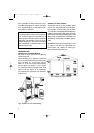
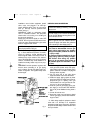
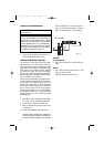
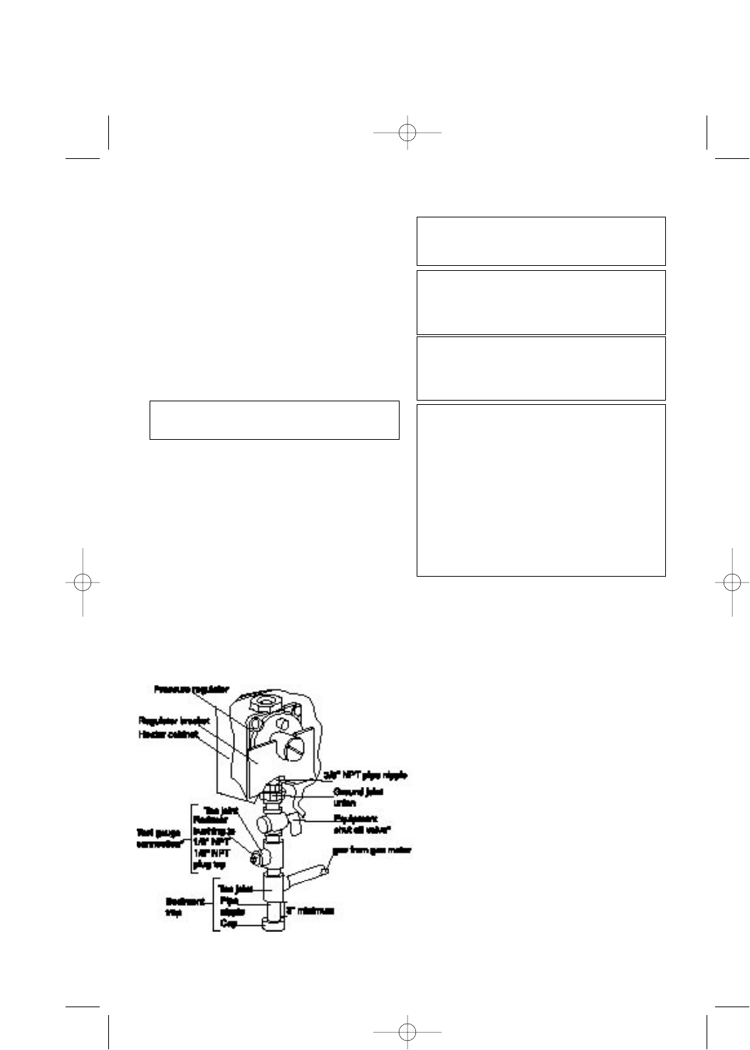
Installation must include equipment shutoff
valve, union, and plugged 1/8” NPT tap.
Locate NPT tap within reach for test gauge
hook up. NTP tap must be upstream from
heater (see fig 7)
IMPORTANT: install an equipment shutoff
valve in accessible location. The equipment
shutoff valve is for turning on or shutting off
the gas to the appliance.
Apply pipe joint sealant lightly to male NTP
threads. This will prevent excess sealant from
going into pipe. Excess sealant in pipe could
result in clogged heater valves.
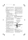
Install sediment trap in supply line as shown in
fig. 7. Place sediment trap where it is within
reach for cleaning. Locate sediment trap
where trapped matter is not likely to freeze. A
sediment trap traps moisture and contami-
nants. This keeps them from going into heater
controls. If sediment trap is not installed or is
installed incorrectly, heater may not run prop-
erly.
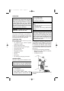
IMPORTANT: hold the pressure regulator with
wrench when connecting it to gas piping
and/or fittings. Do not over tighten pipe con-
nection to regulator. The regulator body could
be damaged.
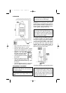
CHECKING GAS CONNECTIONS
1. Disconnect appliance with its appliances
main gas valve (control valve) and equip-
ment shutoff valve from gas supply piping
system. Pressures in excess of 1/2 psig will
damage heater regulator.
2. Cap off open end of gas pipe where
equipment shutoff valve was connected.
3. Pressurize supply piping system by either
opening propane/LP supply tank valve for
propane/LP gas or opening main gas
valve located on or near gas meter for nat-
ural gas, or using compressed air.
4. Check all joints of gas supply piping sys-
tem. Apply a non-corrosive leak detection
fluid to all joints. Bubbles forming show a
leak.
5. Correct all leaks at once.
6. Reconnect heater and equipment shutoff
valve to gas supply. Check reconnected fit-
tings for leaks.
9
WARNING: Use pipe joint sealant that is resist-
ant to liquid petroleum (LP) gas.
WARNING: test all gas piping and connections
for leaks after installing or servicing . Correct all
leaks at once.
WARNING: never use an open flame to check
for a leak. Apply a non-corrosive leak detection
fluid to all joints. Bubbles forming show a leak.
Correct all leaks at once.
CAUTION: For propane/LP gas, make sure
external regulator has been installed between
propane/LP supply and heater. See guidelines
under connecting to Gas Supply, page 8.
* A CSA design-certified equipment shutoff
valve with 1/8” NPT tap is an acceptable
alternative to test gauge connection. Purchase
the optional CSA design certified shutoff valve
from your dealer.
fig. 7
The appliance and its appliance main gas
valve must be disconnected from the gas
supply piping system during any pressure
testing of that system pressures in excess of
1/2 psi (3.5 Kpa).
The appliance must be isolated from the gas
supply piping system by closing its equip-
ment shut-off valve during any pressure
testing of the gas supply piping system at
test pressure equal to or less than 1/2 psi
(3,5 kpa).
WIR 2 26-06-2003 18:21 Pagina 9