


Version B - For Reduction G016.J
®
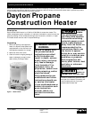
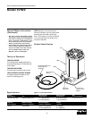
Dayton Operating Instructions and Parts Manual
7
Model 3VH20
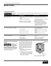
Troubleshooting Chart
Symptom
Possible Cause(s)
Corrective Action
Burner fails to light
Burner lights but goes out when auto-
matic control valve button is released
Maximum burn rate is low
1. Propane supply valve closed on propane
tank(s)
2. Excess flow check valve closed
3. Blockage in burner/valve assembly
4. Piezo ignition system not sparking
1. Not enough warm-up time
2. Low gas pressure
3. Thermocouple loose or bad
4. Bad automatic control valve
1. Low gas pressure
2. Low fuel supply
3. Plugged gas orifices
1. Open propane supply valve slowly
2. Close propane supply valve on propane
tank and reopen slowly
3. Replace burner/valve assembly
4. Assure the ignitor electrode gap is
.120". Check wire lead for damage.
Replace piezo ignitor and/or ignitor
electrode as necessary
1. Relight, hold automatic control valve
button in 45 seconds
2. Check propane tank(s) for proper gas
supply
3. Tighten connection or replace thermo-
couple
4. Replace automatic control valve
1. Check gas supply; check regulator
output
2. Consult propane gas supplier
3. Replace burner assembly
Never attempt to service heater while it is connected to propane supply, operating, or hot. Severe burns
can occur.
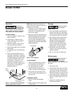
Checking for Correct Burner
Flame
Heater shell, top,
and heated air
from heater is very hot during opera-
tion. Gradually move in closer to
heater to observe flame color. Do not
touch heater shell or top. Do not get
too close to heated air from heater.
Severe burns could occur.
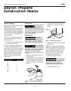
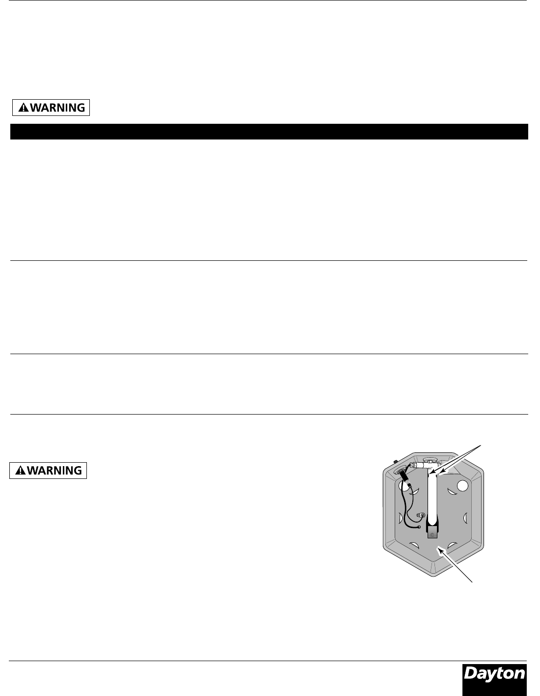
Look through the ventilation holes in the
top of the heater to see the burner flame.
The burner flame should be mostly blue
with slight yellow coloring on the ends. If
the burner flame is mostly yellow, the
primary air openings on the burner tube
under the heater base may be blocked
(See Figure 7).
1. Stop heater (See To Stop Heater on
page 6) and let cool.
2. Turn heater over to locate the primary
air openings on the burner tube (See
Figure 7). Remove any debris blocking
the primary air openings.
Burner
Tube
Primary Air
Opeinings
Figure 7 - Bottom View of Heater