


Version B - For Reduction G016.J
®
3
Model 3VH19
Dayton Operating Instructions and Parts Manual
3VH19
Maximum Supply Minimum Supply
Pressure to Regulator Pressure to Regulator
1/2 PSI 6" w.c.
Theory of Operation
THE FUEL SYSTEM
The gas supply attaches to the heater by a
minimum 3/4 inch i.d. hose or flexible
connector. User must supply hose or
flexible connector. The length should be
no more than 10 feet long. The natural
gas moves through the regulator and out
the nozzle.
THE IGNITION SYSTEM
The piezo ignitor lights the pilot fuel
supply.
THE AUTOMATIC CONTROL SYSTEM
The automatic control valve shuts off the
heater if the flame goes out.
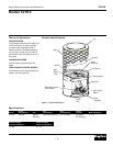
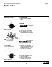
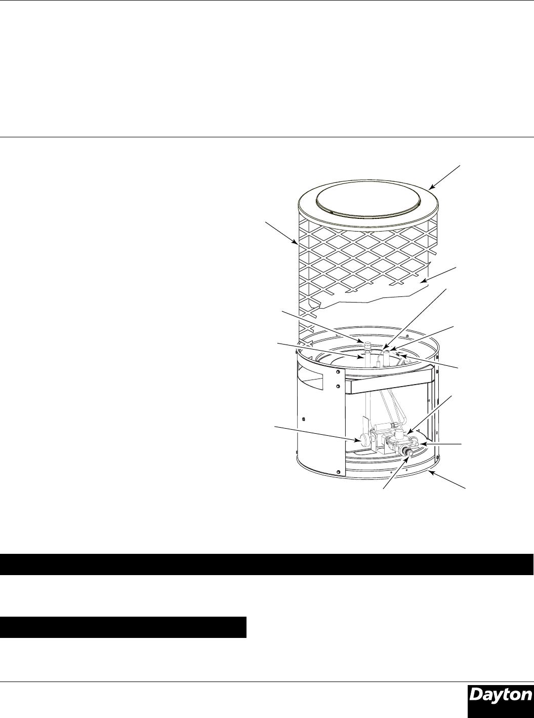
Figure 2 - Product Identification
Product Identification
Specifications
Output Fuel Size Weight
Model Rating Btu/Hr Fuel Consumption LxWxH(Inches) (pounds) Manifold Pressure
3VH19 100,000 Natural 100 Cubic Feet/Hour 16 x 16 x 29.5 23 (Heater) 4" w.c.
Gas Only 27 (Shipping)
Ignitor
Electrode
Pilot Burner
Regulator
Automatic Control
Valve Button
Base
Assembly
Top
Main
Burner
Tube
Nozzle
Emitter
Shell
Piezo Ignitor
Button
Valve
Inlet
Thermocouple