


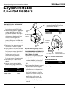

Dayton Operating Instructions and Parts Manual
21
®
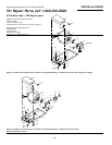
Models 3E358B and 3E359B
3E358B
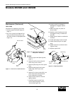
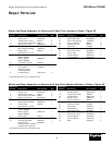
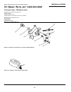
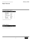
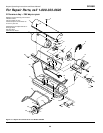
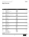
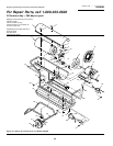
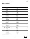
Repair Parts List
Reference
Number Description Part Number Quantity
1 Upper shell 108436-03 1
2 #10-16 x 1/2" Screw *M11084-27 15
3 Combustion chamber and shield M50542-01 1
4 Bushing M30865-02 7
5 Air deflector M50086 5
6 Burner head assembly † 1
7 Photocell assembly M16656-17 1
8 Fan M50121 1
9 Fan guard 108446-01 1
10 Fan switch (Includes cover, reference no. 11) M51336-02 1
11 Fan switch cover M51160-01 1
12 Sleeve M50278 1
13 #10-16 x 3/8" Screw *M11084-26 13
14 Motor & pump assembly † 1
15 Power cord 099896-01 1
16 Fuel line M50295-02 1
17 Ignition boot M50050 1
18 Electronic Ignitor 102482-04 1
19 Lower shell 108437-03 1
20 Clip nut M11271-8 16
21 #12-14 x 1/2" Screw *M11084-3 14
22 Bushing M50104-02 5
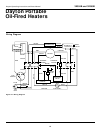
23 Wire harness 099509-01 1
24 Fuel line assembly M50115-01 1
25 Front handle M50062-03 1
26 Fuel cap 097702-01 1
27 Filler neck screen HA2210 1
28 #1/4-20 x 2
1
/4" Screw *HC4-18C 6
29 #1/4-20 x 1
1
/2" Bolt *M51043-01 2
30 Rear handle M50062 1
31 Fuel tank 098513-05 1
32 Wheel support frame M50063 1
33 Axle M18774 1
34 1/4-20 Hex lock nut *NTC-4C 8
35 Wheel M50389 2
36 5/32 x 1 1/4" Cotter pin *C5-10C 2
37 5/8" Flatwasher WP-10C 4
38 Wheel spacer M50296 2
39 Drain plug M27417 1
40 Thermostat 099895-01 1
41 #10-16 x 1/2" Screw *M15823-27 10
42 #10-16 x 3/4" Screw M11084-29 2
General information decal 101685-05 1
(*) Standard hardware item, available locally.
(†) Not available as complete assembly.
( ) Not shown.