


4. 5.
For maximum range between the transmitter and receiver, the receiver
should be mounted horizontally on a wall and as high off the fl oor as pos-
sible. Although the maximum range is about 3000 feet, things such as hills,
trees, metal siding and stucco can all reduce the range.
CODING THE RECEIVER
1. Open the receiver case by inserting a small screw driver into one of the
pry notches on the side of the case.
2. Gently lift off the front cover.
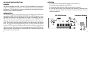
3. Locate the 8 dip switches (5) on the
receiver and make sure they set
identically to the fi rst 8 dip switches (6) on the transmitter. Note: If more
than one transmitter is used with the receiver, the fi rst 8 dip switches of all
transmitters must match the 8 dip switches of the receiver.
NOTE: Whenever a change is made to the time jumper or the dip switches,
the receiver must be turned “OFF” and then back “ON” to operate properly.
CODING THE TRANSMITTER
1. Locate the dip switches in the 3000 series transmitter. (refer to trans-
mitter manual)
2. The fi rst 8 dip switches (6) are for the frequency setting (256 combina-
tions). Set the fi rst 8 switches to match the 8 switches in the receiver.
3. Switches 9 & 10 (7) are for the zone/channel setting on the transmitter.
The four zones are as follows:
TONE, RELAY AND VOLTAGE OUTPUT
1. Each of the four transmitter zones (selectable by switch 9 & 10) will
sound a tone and activate the corresponding relay on the receiver.
2. Each of the form “C” relays is rated for 24 VDC at 3 Amp maximum current.
3. The 12 VDC output will activate when the transmitter is set to zone 1. The
voltage duration will last for four seconds and has a maximum current of
400mA.
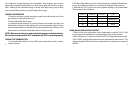
Switch 9 Switch 10 Channel Tune
ON ON 1+12VDC Classical
OFF ON 2 Westminster
ON OFF 3 Ding Dong
OFF OFF 4 Whistle