


8.
{
{
4
3
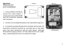
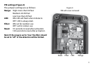
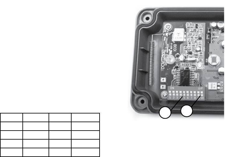
Figure 5
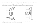
Coding the transmitter:
Note: The transmitters and receivers are preset
at the factory. DO NOT change settings, unless
changing the tune or experiencing false signals.
1.
Locate the dip switches in the DCMT-2500
circuit board (Figure 5).
2. The rst eight dip switches are for the
frequency setting (256 combinations). Set
switches 1-8 (Figure 5-3) to match the eight
switches in the receiver.
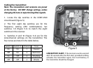
3. Switches 9 and 10 (Figure 5-4) are for the
zone/channel settings on the transmitter. The
four zones are listed in the table below.
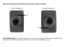
LOW BATTERY ALERT: If the receiver sounds a second
alert 30 seconds after the rst alert, provided nothing
activates the transmitter again, the 9-volt battery in
the transmitter should be changed.
Switch 9 Switch 10
Channel
Tune
On On 1
Classical
O On 2
Westminster
On O 3
Ding Dong
O O 4 Whistle