


12
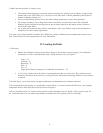
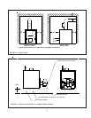
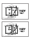
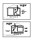
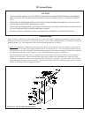
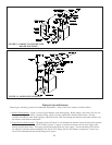
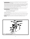
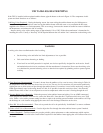
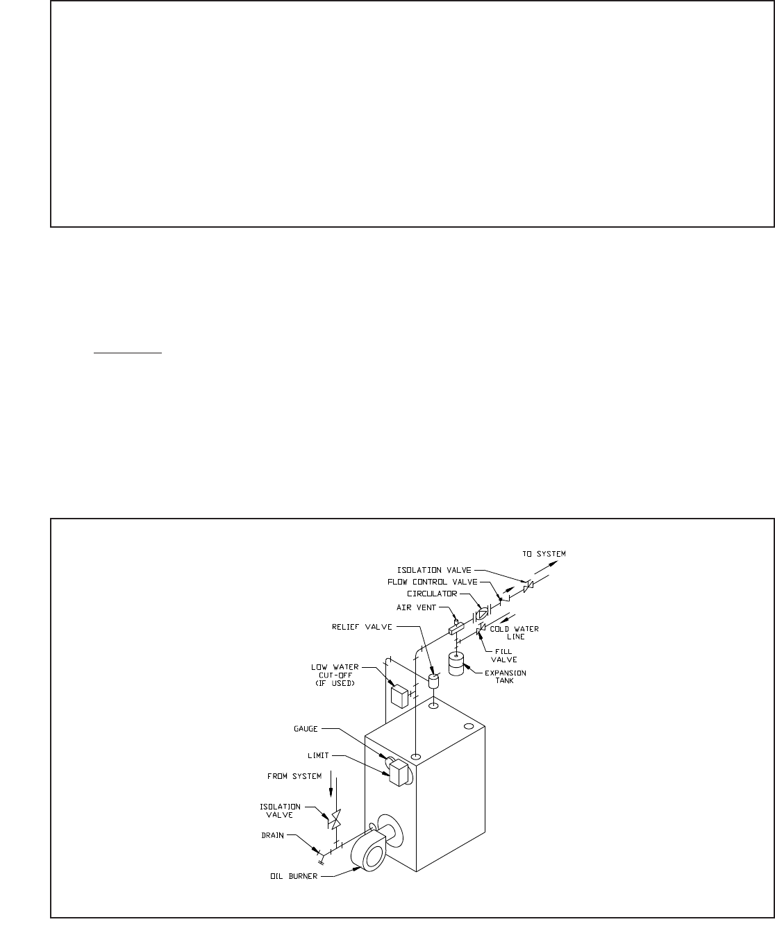
FIGURE 10: STANDARD BOILER PIPING
CAUTION
• INSTALL BOILER SO THAT ALL ELECTRICAL COMPONENTS ARE PROTECTED FROM WATER (DRIPPING,
SPRAYING, RAIN, ETC.) DURING APPLIANCE OPERATION AND SERVICE (CIRCULATOR REPLACEMENT,
ETC.).
• OPERATION OF THIS BOILER WITH CONTINUOUS RETURN TEMPERATURES BELOW 120°F CAN CAUSE
SEVERE HEAT EXCHANGER CORROSION DAMAGE.
• OPERATION OF THIS BOILER IN A SYSTEM HAVING SIGNIFICANT AMOUNTS OF DISSOLVED OXYGEN CAN
CAUSE SEVERE HEAT EXCHANGER CORROSION DAMAGE.
• DO NOT USE TOXIC ADDITIVES, SUCH AS AUTOMOTIVE ANTIFREEZE, IN A HYDRONIC SYSTEM.
Standard Piping
Figure 10 shows typical boiler system connections on a single zone system. Additional information on hydronic system
design may be found in Installation of Residential Hydronic Systems (Pub. #200) published by the Hydronics Institute in
Berkeley Heights, NJ. The components in this system and their purposes are as follows:
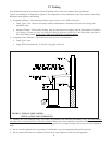
1) Relief valve (Required) - Mount the relief valve on the top left side of the boiler as shown in Figure 10 using the 3/4”
nipple provided. The relief valve shipped with the boiler is set to open at 30 psi. This valve may be replaced with one
having a pressure up to the “Maximum Allowable Working Pressure” shown on the rating plate. If the valve is replaced,
the replacement must have a relief capacity in excess of the DOE heating capacity for the boiler.
Pipe the discharge of the relief valve to a location where water or steam will not create a hazard or cause property
damage if the valve opens. The end of the discharge pipe must terminate in an unthreaded pipe. If the relief valve
discharge is not piped to a drain, it must terminate at least 6 inches above the floor. Do not run relief valve discharge
piping through an area that is prone to freezing. The termination of the relief valve discharge piping must be in an area
where it is not likely to become plugged by debris.
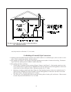
VII System Piping
11