


3
IIIBeforeInstalling
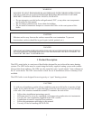
1) Safe, reliable operation of this boiler depends upon installation by a professional heating contractor in
strict accordance with this manual and the authority having jurisdiction.
• In the absence of an authority having jurisdiction, installation must be in accordance with this manual
and Installation of Oil-Burning Equipment (ANSI/NFPA 31).
• Where required by the authority having jurisdiction, this installation must conform to the
Standard for Controls and Safety Devices for Automatically Fired Boilers (ANSI/ASME CSD-1)
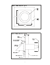
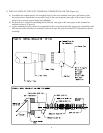
2) Read Section VI to verify that the maximum combustion air and exhaust pipe lengths will not be
exceeded in the planned installation. Also verify that the vent terminal can be located in accordance with
Section VI. Note: The maximum wall thickness through which the terminal can be installed is 12”.
3) Make sure that the boiler is correctly sized:
• For heating systems employing convection radiation (baseboard or radiators) use an industry
accepted sizing method such as the I=B=R Heat Loss Calculation Guide (Pub. #H21 or #H22)
published by the Hydronics Institute in Berkely Heights NJ.
• For new radiant heating systems refer to the radiant tubing manufacturer’s boiler sizing guidelines.
• For systems including a Crown Mega-Stor indirect water heater, size the boiler to have either the DOE
Heating Capacity required for the Mega-Stor or the net rating required for the heating system,
whichever results in the larger boiler.
• For systems that incorporate other indirect water heaters, refer to the indirect water heater manufac-
turer’s instructions for boiler output requirements.
4) Do not install this boiler at altitudes above 2000ft.
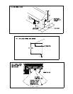
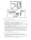
5) Inspect shipment. This boiler is shipped in three pieces:
a) Wire-bound crate with boiler
b) Vent terminal carton – Includes terminal, vent adapters, inlet piping and hardware
c) Vent pipe carton - Includes exible vent pipe.
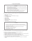
IVLocatingtheBoiler
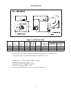
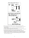
1) Observe the clearances below. Top, side and rear clearances are from jacket. Front clearance is from
burner door.
To Combustible Construction To Non-Combustible Construction
Front 24 15
Left* 6 2-1/2
Right 6 1
Rear Determined by clearance to Flexible Vent Pipe (below)
Top 24 24
Terminal 0 0
Flexible Vent Pipe 3 0
* 14 inch clearance required to open door.
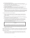
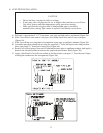
2) Boiler must be installed on a non-combustible surface.
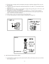
3) Boiler must be located so that the 15-foot vent pipe supplied with the boiler will reach the
planned
terminal location. Approximately 1.3 feet of pipe length is used up in making a 90-degree bend
(Fig 11). See Section V for more information on venting requirements.