


4
3) Make sure that the boiler is correctly sized. Use an industry accepted sizing method such as the I=B=R Installation Guide
for Residential Hydronic Heating Systems and I=B=R Heat Loss Calculation Guide (Pub. #H21 or #H22) published by the
Hydronics Institute in Berkeley Heights, NJ.
4) In some cases, boilers installed at altitudes above 2000ft may require a different burner configuration from that at sea level.
Consult the local Crown representative for more information.
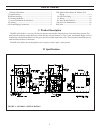
IV Locating the Boiler
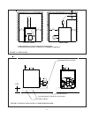
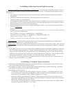
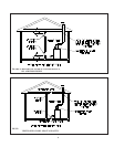
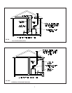
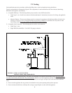
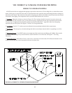
1) Clearances:
• Observe the minimum clearances shown below. Except as noted, these clearances apply to all combustible
construction, as well as noncombustible walls, ceilings and doors. Also see Figure 2.
Front – 24”
Left Side – 6” (24” for Boilers Equipped with Float Type Low Water Cut-offs)
Right Side – 6” (24” for Boilers Equipped with Tankless Heaters)
Rear – 6” (24” for boilers connected to indirect water heaters)
Top – 6”
Single Wall Chimney Connector (to combustible construction) - 18”
• A 24” service clearance from the jacket is recommended from the top of the boiler. This clearance may be
reduced to that shown above; however, servicing the boiler will become increasingly difficult as this clearance is
reduced.
• A 24” service clearance is required on the left side of KSZ series boilers equipped with float type low water cut-
offs. This is to facilitate low water cut-off maintenance.
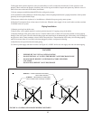
2) If listed Type L vent is used, follow vent pipe manufacturer recommendations for minimum clearances.
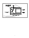
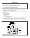
3) Do not install this boiler directly on a combustible surface. Where it is desired to install the KSZ over a non-carpeted
combustible surface, install the boiler on the base shown in Figure 3.
4) Do not install this boiler in a location where gasoline or other flammable vapors or liquids will be stored or used. Do not
install this boiler in an area where large amounts of airborne dust will be present, such as a workshop.
V Air for Combustion and Ventilation
Sufficient fresh air must be supplied for combustion and ventilation. Provisions for combustion and ventilation air for oil
burning equipment must be made in accordance with Section 1.5, Air for Combustion and Ventilation, in the latest edition of
Installation of Oil Burning Equipment (ANSI/NFPA 31).
To ensure an adequate supply of air for combustion, ventilation and flue gas dilution, start by determining whether the boiler
is to be installed in a building of unusually tight construction. A building of unusually tight construction is defined as having
all of the following features:
• Walls and ceilings exposed to outside atmosphere have a continuous water vapor retarder with a rating of 1 perm or
less with openings gasketed and sealed.
• Weather stripping has been added on openable windows and doors.
• Caulking and sealants are applied to areas such as joints around window and door frames, between sole plates and
floors, between wall-ceiling joints, between wall panels, at penetrations for plumbing, electrical, and gas lines, and at
other openings.
3