


25
24
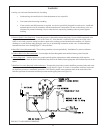
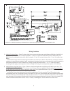
Sequence of Operation, Intermittent Ignition, Less Tankless Heater
1) When the boiler is energized, 24 volts is immediately applied to terminals “1” (blue) and “4” (yellow) on the vent damper.
Assuming that there is no call for heat, and that the damper switch is in the “automatic” position, the damper will close.
2) A call for heat from the thermostat energizes relay coil 1R (the relay on the L8148E), causing contacts 1R1 and 1R2 to make.
Contact 1R1 starts the circulator. Contact 1R2 sends power to the high limit.
3) Assuming that the high limit is made, current will flow to pin terminal #2 (orange) at the vent damper and the damper will open.
4) Once the vent damper is fully open, an end switch inside the damper will make, energizing pin #3 (red) at the damper. This pin
is connected through the damper harness to terminal “B1” on the L8148E. At this point in the operating sequence, 24 volts is
present across “B1” and “B2”.
5) Under normal conditions, the flame roll-out switch and blocked vent switch are made. Voltage will therefore immediately appear
across the “24V” and “24V (GND)” terminals on the ignition module.
6) Upon application of voltage across the “24V” and “24V (GND)” terminals, the ignition module will start an ignition spark at the
pilot and apply 24 volts across the pilot valve (terminals “PV” and “MV/PV”).
7) Once the pilot is established, the pilot flame will act as a diode, converting the AC current at the electrode to a half wave DC
current at the pilot’s ground strap. This DC current flows through the boiler to the “GND (BURNER)” connection on the
ignition module. For the ignition module to recognize that a pilot flame is present, the DC current flowing into this terminal
must be in excess of approximately 1.0 uA.
8) Once the ignition module detects the presence of a pilot flame, voltage is applied across the main valve (terminals “MV” and
“MV/PV”), opening the valve and establishing main flame.
9) The way in which the ignition module handles failure to establish pilot or the loss of an already established pilot depends
upon the exact ignition module supplied with the boiler. For more information on module operation, consult the ignition
module instructions supplied with the boiler or the local Crown representative.
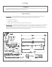
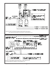
Sequence of Operation, Intermittent Ignition, With Tankless Heater
1) When the boiler is energized, 24 volts is immediately applied to terminals “1” (blue) and “4” (yellow) on the vent damper.
Assuming that there is no call for heat, and that the damper switch is in the “automatic” position, the damper will close.
2) If the boiler water temperature is less than the low limit setting minus the differential setting, terminals “R” and “B” in the
L8124E are made through the low limit switch. The low limit switching action is SPDT with “R” being common. “R” and “W”
are therefore open whenever “R” and “B” are made. This means that while “R” and “B” are made relay coil R1 is deenergized,
regardless of whether or not there is a call for heat. The circulator will therefore not operate if the boiler water temperature is
too low to generate domestic hot water.
3) Assuming that the high limit is made, current will flow to terminal “B1” on the L8124E and then to terminal “2” (orange) at the
vent damper and the damper will open.
4) Once the vent damper is fully open, an end switch inside the damper will make, energizing pin #3 (red) at the damper. The red
wire from this pin runs to the flame rollout switch.
5) Under normal conditions, the flame roll-out switch and blocked vent switch are made. Voltage will therefore immediately appear
across the “24V” and “24V (GND)” terminals on the ignition module.
6) Upon application of voltage across the “24V” and “24V (GND)” terminals, the ignition module will start an ignition spark at the
pilot and apply 24 volts across the pilot valve (terminals “PV” and “MV/PV”).
7) Once the pilot is established, the pilot flame will act as a diode, converting the AC current at the electrode to a half wave DC
current at the pilot’s ground strap. This DC current flows through the boiler to the “GND (BURNER)” connection on the
ignition module. For the ignition module to recognize that a pilot flame is present, the DC current flowing into this terminal
must be in excess of approximately 1.0 uA.
8) Once the ignition module detects the presence of a pilot flame, voltage is applied across the main valve (terminals “MV” and
“MV/PV”), opening the valve and establishing main flame.
9) The way in which the ignition module handles failure to establish pilot or the loss of an already established pilot depends
upon the exact ignition module supplied with the boiler. For more information on module operation, consult the ignition
module instructions supplied with the boiler or the local Crown representative.
10) The boiler will fire until the boiler water temperature is approximately equal to the low limit setting. Once the water temperature
reaches this point, “R” and “B” open and “R” and “W” make. At this point, a call for heat from the thermostat will energize 1R,
making contacts 1R1 and 1R2. Contacts 1R1 energize the circulator. Contacts 1R2 switch current from the “hot” side of the
transformer secondary to the high limit switch. If the high limit is made, current flows to terminal “B1” and the ignition
sequence is then the same as it is for a call for burner operation from the low limit (see (3) above).