


Only qualified service personnel shall perform installation and service.
3
1) Remove the oil burner from the shipping carton and remove any shipping
materials adhering to the burner. Collect and save the burner mounting gasket
and any instructions furnished with the burner.
2) If it is necessary to adjust the heating capacity of the furnace, by changing the oil
burner nozzle, refer to the following directions.
a) The oil nozzle is factory installed in the oil burner. To change the oil nozzle,
remove the nozzle through the front end of the burner air tube. Consult the oil
burner manufacturer’s operating instructions (included with the burner) for
detailed instructions on this procedure.
b) Install an appropriate replacement nozzle of the correct size, spray angle,
and spray type. Refer to the Specification Sheets, in Appendix C of the
furnace instruction manual, for nozzle recommendations.
3) On highboy furnace models, remove the burner access panel. This panel will be
the upper access panel on the front of the furnace. On lowboy models, remove
the front access panel. On horizontal / counterflow models, the burner is
mounted on the front surface of the furnace.
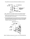
4) Remove the three (3), 5/16 in. brass hex machine screw nuts and the three (3)
steel flat washers from the threaded studs protruding through the burner
mounting plate on the furnace. Retain this hardware for later reuse.
5) Rough handling of the furnace may occur while in transit. Under some
conditions, the combustion chamber can shift out of position. The chamber
should seat properly on the base of the heat exchanger. Check for proper
alignment of the burner air tube with the circular opening in the combustion
chamber and trial fit the burner to check the insertion depth of the oil burner into
the combustion chamber. It may be necessary to remove the burner mounting
plate to get sufficient access to the chamber.
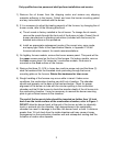
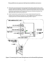
The end of the burner air tube should be inserted no farther than 1/4 inch
back from the inside surface of the combustion chamber, refer to Figure 1.
DO NOT allow the burner head, at the end of the burner air tube, to physically
touch or protrude into the chamber. High temperatures in the combustion
chamber can result in damage to the tube, the burner head, or both. A distance
greater than 1/4 inch back from the inside chamber wall may cause oil spray
impingement on the combustion chamber wall and subsequent sooting and the
formation of carbon char deposits.