


9
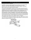
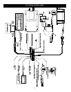
WIRING
NOTE: Some Options Need to Be Pre-programmed From Crimestopper prior to
installing the unit.
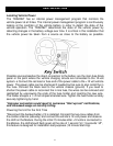
Pin 1 Black: Chassis Ground Input
THIS WIRE MUST BE CONNECTED TO THE CHASSIS METAL OF THE VEHICLE.
Scrape away any paint or dirt to ensure a good connection.
Pin 2 Green: Starter Disable (-) (Output #2) Requires Relay
This wire has a negative output to hook up to optional relay. See wiring diagram for
connection.
Pin 3 Blue: GEO Fence (Optional) (-) Input #2
Connect wire to momentary switch 2 sec input to trigger for GEO fence or 15 sec
input to trigger alarm.
Pin 4: Empty
Pin 5 Red: Battery Back Up Power (Input)
Pre-wired to connector for battery back up.
Pin 6 White: Overheat Trigger/ Road Side Assistance (-) Input #3
This wire needs 2 minute trigger for Overheat or 2 sec trigger for Road Side
Assistance. Pre-programmed for Overheat.
Pin 7: Empty
Pin 8 Brown: Ignition Input #4 (+)
This wire must be connected to an Ignition source.
Pin 9: Empty
Pin 10 Purple: LED (Optional) (+) Output
This wire connects to optional LED for visual status of RSA or GEO Fence.
Pin 11 Yellow: Door Unlock Output (-)
This wire connects to the door unlock circuit. This wire is a negative output and may
require additional relays to interface with different door lock circuits