


WIRING
WHITE/RED WIRE: (-) REMOTE OUTPUT #2 (Optional, Requires Relay)
This wire provides a momentary (-) Negative auxiliary Output when Button #4 is pressed and held for at least 2
seconds. Connect this wire to terminal 85 of a relay to operate an AUX device or function. Connect terminal 86 or
the relay to +12 Volts constant. Connect terminal 87 to 12Volts or Ground depending to the type of circuit needed.
Connect Terminal 30 to the AUX device’s activation wire. This output will stay activated as long as the button is
held down.
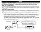
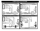
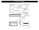
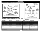
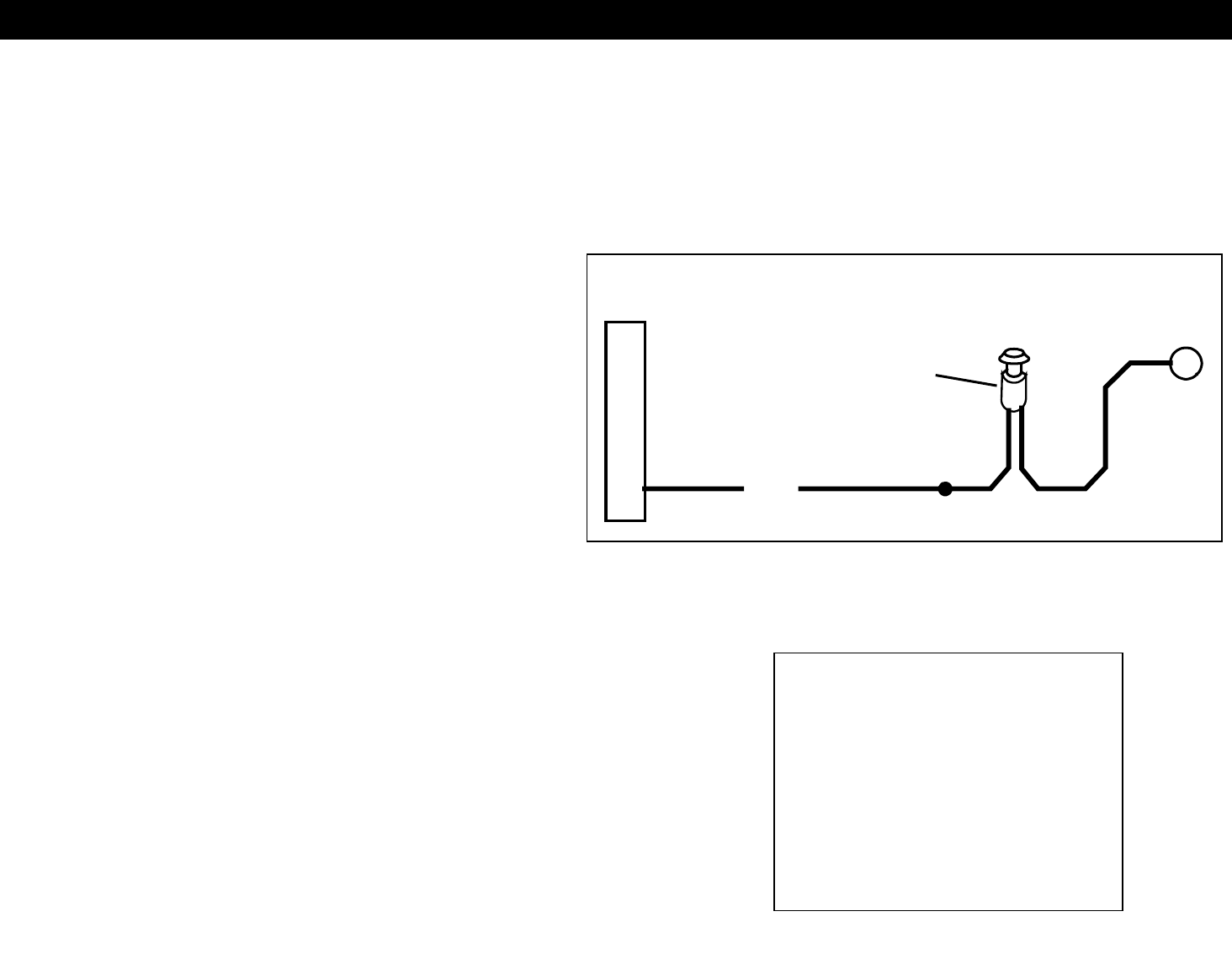
PINK WIRE: (+) CARJACK INPUT
Connect to a push button, toggle switch, or to a +12
Volt source to selectively activate Car Jack protection
features - See diagram on next page for example
wiring configuration. This wire is used to activate a
passive carjack trigger even if the Carjack features
are not turned on in the programming options. A
Carjack countdown will begin under the following
conditions: Ignition is ON (vehicle is running), the
button or toggle switch is pressed, and a door opens
& closes. Upon these 3 events, in that order, the
alarm will start a Carjack countdown. See “Carjack
protection” section on page
+
+12 V
PINK
OPTIONAL CAR JACK WIRING: SWITCH
HIDDEN BUTTON or
TOGGLE SWITCH
(Not Included)
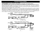
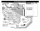
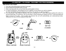
2-PIN PLUG (SMALL): LED INDICATOR (RED FLASHING LIGHT)
TIP: The Sensor supplied with
this system does not require
any additional wiring, simply
mount the sensor in a suitable
location, plug in, and adjust to
the desired levels o
f
sensitivity. The Black dial is
for Pre-warn level and White
dial is for Shock tri
gg
er.
2-PIN PLUG (MEDIUM): PROGRAM/OVERRIDE PUSH BUTTON
4-PIN SENSOR PLUG:
RED WIRE SENSOR +12V POWER
BLACK WIRE SENSOR GROUND
BLUE WIRE: NEG. WARN AWAY
WHITE WIRE: NEG. TRIGGER
3-PIN BLUE SENSOR #2 PLUG: (For adding additional sensors)
PIN 1: SENSOR +12V POWER
PIN 2: NEGATIVE (-) TRIGGER
PIN 3: SENSOR GROUND
5