


iLux™ Expansion Module Crestron CLS-EXP-DIMU
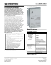
Physical Description
This section provides information on the connections,
controls and indicators available on the CLS-EXP-DIMU.
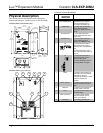
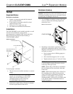
CLS-EXP-DIMU Overall Dimensions
8.82 in
(22.40 cm)
6.39 in
(16.23 cm)
5.79 in
(14.71 cm)
4.99 in
(12.67 cm)
Ø 0.19 in
(Ø 0.48 cm)
8.31 in
(21.11 cm)
7.31 in
(18.57 cm)
Ø 0.25 in
(Ø 0.64 cm)
0.50 in
(1.27 cm)
3.18 in
(8.08 cm)
3.07 in
(7.80 cm)
1.64 in
(4.17 cm)
1.64 in
(4.17 cm)
2.02 in
(5.21 cm)
1.56 in
(3.96 cm)
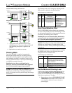
CLS-EXP-DIMU (cover removed)
PHASE
STATUS
POWER
S1
ON
12 21
ON
S2
1
7
12
8 9
2 3
10 11
4 5 6
Connectors, Controls & Indicators
# CONNECTORS,
CONTROLS &
INDICATORS
DESCRIPTION
1 FLUORESCENT
OFF THRESHOLD
(1) Recessed screwdriver-
adjustable trim pot, adjusts
minimum brightness level.
Covered by removable cap.
2 PHASE LED (1) Yellow LED behind front
panel; illuminates when
operating in Reverse Phase
mode.
3 STATUS LED (1) Red LED behind front
panel; illuminates when load
output is on.
4 POWER LED (1) Green LED behind front
panel; indicates power is
applied to the HOT terminal.
5 S2
21
ON
(1) Two-position DIP switch
behind front panel; used to
select the zero cross detection
filter.
For more information, refer to
“Zero Cross Detection Filter” on
page 6.
6 S1
ON
12
(1) Two-position DIP switch
behind front panel; used to
select dimming mode.
For more information, refer to
“Dimming Mode” on page 6.
7 CTRL (1) Captive screw terminal, for
control input from CLS-Series,
CLW-Series* dimmers,
CLX-DIM (all versions), or other
Crestron incandescent
dimmers.
8 NEUT (INPUT) (1) Captive screw terminal, for
neutral connection for control
input.
9 DIM OUT (1) Captive screw terminal for
dimmed output to the load.
10 HOT (1) Captive screw terminal, for
line power input.
11 NEUT (OUTPUT) (1) Captive screw terminal,
neutral connection for line
power input and load.
12 GROUND (1) Chassis ground bus bar.
* CLW-Series device must have a dedicated neutral.
4 • Terminal Block & Module: CLTI- & CLXI-2DIM8 Installation Guide – DOC. 6682B