PREPARATION
BASIC TOOLS AND MATERIALS NEEDED
Pipe Wrenches Screwdriver
Hacksaw Check Valve
Adjustable Wrench Teflon Tape
Knife
INSTALLATION (Continued)
Suction Pipe
iTee
and Plug
NOTICE: Depth to water must not be more than 20'.
1. Long runs and many fittings increase friction and reduce
flow. Locate pump as close to water source as possible:
use as few elbows and fittings as possible.
2. Be sure water is clear of sand. Sand will plug the pump
and void the warranty.
3. Protect pump and all piping from freezing. Freezing will
split pipe, damage puthp and void the warranty. Check
locally for frost protection requirements (usually pipe
must be 12" below frost line and pump must be insu-
lated).
4. Be sure all pipes and foot valve are clean and in good
shape.
5. No air pockets in suction pipe.
6. No leaks in suction pipe. Use Teflon tape or Plasto-Joint
Stik' to seal pipe joints.
7. Unions installed near pump and water source v/ill aid in
servicing. Leave room to use wrenches.
8. IAWARNING]Pump body may explode if used as a
booster pump. DO NOT use in a booster application.
' Lake Chemical Co., Chicago, Illinois.
INSTALLATION
NOTICE: Use the installation method below which matches
your well type.
CASED WELL INSTALLATION
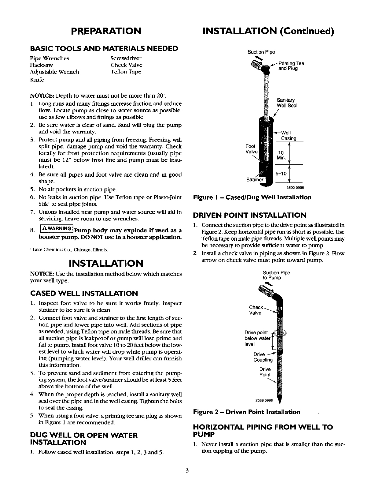
1. Inspect foot valve to be sure it works freely. Inspect
strainer to be sure it is dean.
2. Connect foot valve and strainer to the first length of suc-
tion pipe and lower pipe into well. Add sections of pipe
as needed, using Teflon tape on male threads. Be sure that
all suction pipe is leakproof or pump will lose prime and
fail to pump. install foot valve 10 to 20 feet below the low-
est level to which water v/ill drop while pump is operat-
ing (pumping water level). Your well driller can furnish
this information.
3. To prevent sand and sediment from entering the pump-
ing system, the foot valve/strainer should be at least 5 feet
above the bottom of the well.
4. When the proper depth is reached, install a sanitary well
seal over the pipe and in the well ca_mg. Tighten the bolts
to seal the casing.
5. When using a foot valve, a priming tee and plug as shown
in Figure 1 are recommended.
DUG WELL OR OPEN WATER
INSTALLATION
1. Follow cased well installation, steps 1, 2, 3 and 5.
Sanitary
Well Seal
/
Foot
Valve
Strainer
2590 0996
Figure I - Cased/Dug Well Installation
DRIVEN POINT INSTALLATION
1. Connect the suction pipe to the drive point as illustrated in
Figure 2. Keep horizontal pipe run as short as possible. Use
Teflon tape on male pipe threads. Multiple well points may
be necessary to provide suf_cient water to pump.
2. Install a check valve in piping as shown in Figure 2. Flow
arrow on check valve must point toward pump.
Suction Pipe
to Pump
Check_
Valve
Drive point 1_
below waterT
level __
Drive
Coupling
Drive
Point
2589 0996
Figure 2 - Driven Point Installation
HORIZONTAL PIPING FROM WELL TO
PUMP
1. Never install a suction pipe that is smaller than the suc-
tion tapping of the pump.
