


Page 7
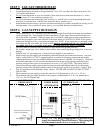
STEP 3 - LOCATE THERMOSTAT
1. Thermostat must be installed in same room as heater.
2. Locate thermostat on an inside wall approximately 5 feet {153 cm} above the floor and at least 6 feet
{183 cm}from the heater.
3.
Do not locate thermostat so as to be effected by heat from sources other than the heater (i.e. direct
sunlight, lamps, T.V. sets, radiators, registers, etc.).
4. Do not locate thermostat in unusually cool locations (i.e. outside wall, on a wall separating the heated
area from an unheated area, in drafts from stairwells, doors, windows, etc.).
5. Install thermostat where there is good air circulation and where it is readily accessible for wiring, service
and adjustment. Never install in a corner, alcove, over or behind furniture or behind a door.
STEP 4 - GAS SUPPLY ROUGH-IN
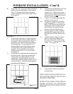
1. An inch and a half (1-1/2”) opening is provided toward the right front of the liner bottom for installation
of the gas supply line. This opening facilitates installation of a gas supply line located inside the room
where the heater is installed. If the gas supply line is located in a stud space or other concealed area
consult the gas supplier, local code officials or the latest edition of ANSI Z223.1/NFPA 54 for special
instructions and approval for a concealed gas supply line. NOTE: If gas supply line is concealed, it must
be brought into the room under the heater as there
must be a manual shut-off valve installed in the
gas supply line that is accessible from inside the room where the heater is installed.
2. The valve must be connected only by means of a pipe union of the ground joint type.
3. Mr. Installer, support gas valve, with a second wrench, when connecting the gas supply line, to prevent
damage.
4. Install at least 3/8” gas supply line. Contact local gas supplier if any questions.
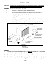
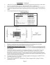
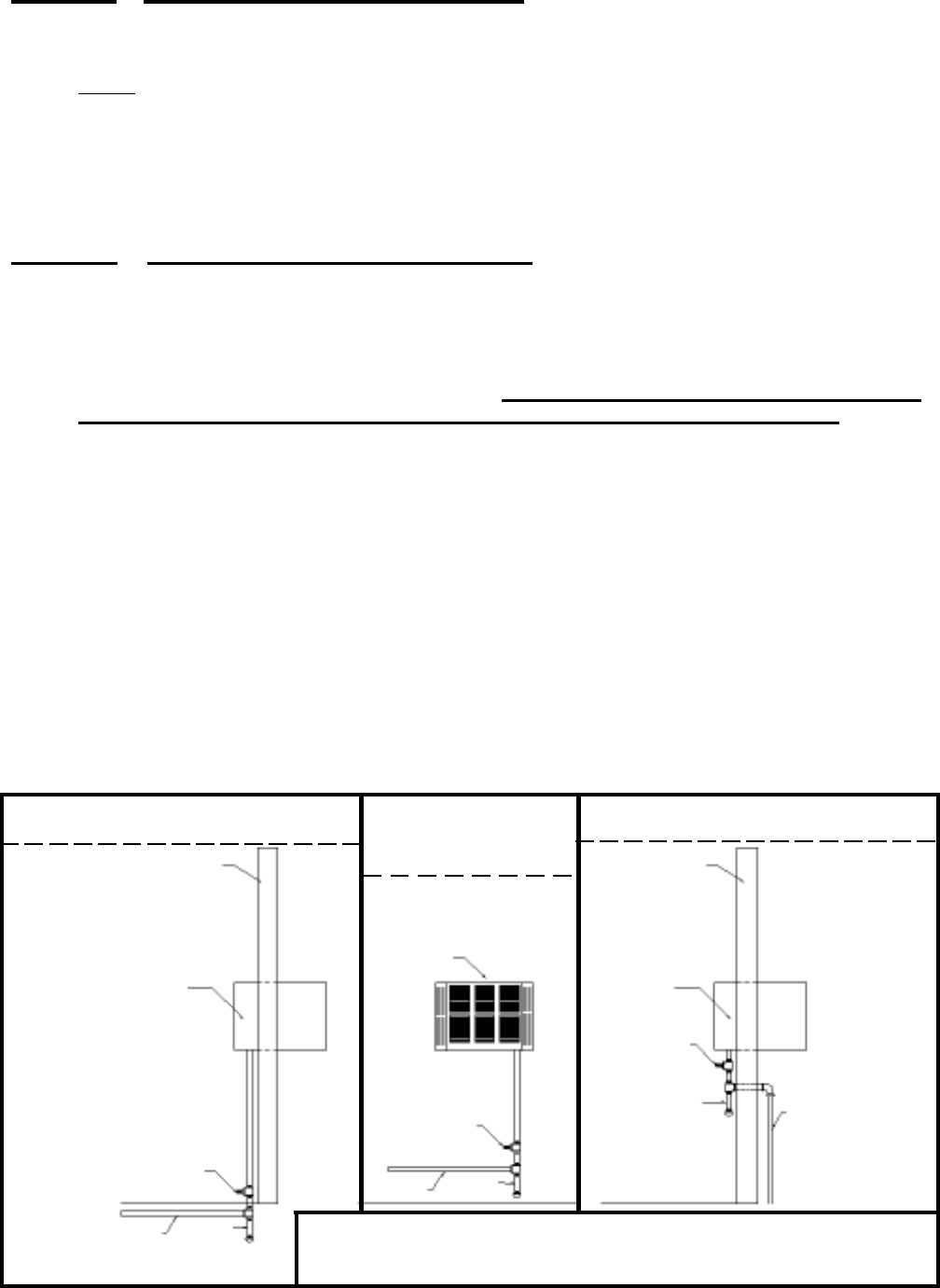
5. Install a drip leg in gas supply line immediately upstream from the gas connection to heater. (see local
codes), and provide a 1/8” N.P.T. plugged tapping, accessible for test gauge connection and an indi-
vidual manual shut off valve accessible within room where heater is installed. (See Figure 4). The heater
and its individual shut off valve must be disconnected from the gas supply piping system during any
pressure testing of that system at test pressures in excess of 1/2 psig (3.5Pa). The heater must be
isolated from the gas supply piping system by closing its individual manual shut off valve during any
pressure testing of the gas supply piping system at test pressures equal to or less than 1/2 psig (3.5Pa).
6. Test all connections for leaks using a soapy solution. NEVER USE AN OPEN FLAME TO TEST
FOR LEAKS.
7. The maximum inlet gas supply pressure for natural or L.P./Propane gas is 1/2 p.s.i. or 14” w.c.
8. The minimum inlet gas supply pressure for the purpose of adjustment is 4.5” w.c. for natural gas or
11.0” w.c. for L.P./Propane gas.
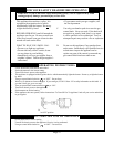
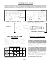
FIGURE 4
WOW Heater
Outside Wall
Outside Wall
WOW Heater
Floor
Floor
Floor
Gas Supply
Gas Supply
Drip
Leg
Drip
Leg
Drip
Leg
Gas Supply
Manual shut off valve must
be in room with heater
Manual shut off
valve must be in
room with heater
Manual shut
off valve must
be in room with
heater
GAS SUPPLY FROM
CRAWL SPACE
GAS SUPPLY THROUGH
OUTSIDE WALL
GAS SUPPLY
INSIDE ROOM
WITH HEATER
WOW Heater
NOTE: 1/8” NPT plugged tapping must be provided in gas
supply line immediately ahead of the heater. This tapping may
be in the manual cutoff valve or in a separate fitting.