


Page 10
INSTALLING THROUGH A FRAME WALL
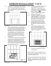
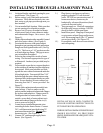
NOTE: The WOW25 models will install between wall studs on 16” centers. The WOW40 will attach to a stud
on either the right or left side. The opposite stud must be cut out of the opening and 1-1/2” below the cutout. You
must then install a 2”-by your wall thickness plate on top of the cut stud and secure to the remaining stud. This plate
will cover the opening inside the wall, front to back, and provides support as well as a foundation that will be used
to secure the bottom of the heater.
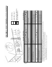
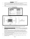
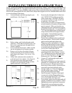
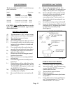
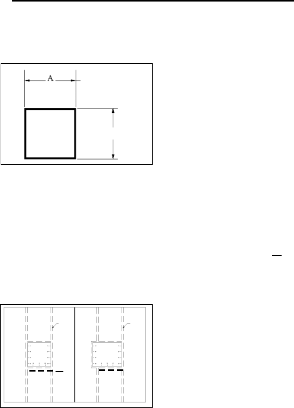
A.) At desired height, mark hole opening for your
model heater. (See Figure 11).
B.) Before cutting, verify both inside and outside
clearances. Verify that no electrical wires, con-
duit, water or gas pipes pass through the area
you have marked.
C.) Cut out marked hole location. Make sure that
the cut out opening is level inside to outside.
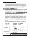
D.) Remove six (6) screws from back of heater
which secure back of outer cabinet to intake
and exhaust tube flanges. Save screws. (See
Figure 5).
E.) Gently slide combustion tube assembly for-
ward and out of outer cabinet. (See Figure 6).
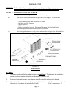
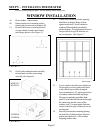
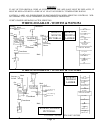
F.) From inside the room, slide outer cabinet
through cut out opening until flanges are flush
against inside wall. (See Figure 12).
FIGURE 12
WOW 25
WALL
STUD
WOW 40
WALL
STUD
One stud
must be
cut
M u s t
install
b a s e
plate
G.) Secure in place through side of cabinet into
stud. WOW253/254 will be secured into
studs on both sides. WOW403/404 must
be secured to stud on one side, can be left
or right side. (See Figure 12).
H.) From outside secure the two support brack-
ets to the outside wall, anchors (not provided)
may be required. Make sure brackets are
flush against the outer cabinet bottom and un-
der the left and right sides. You must drill four
7/64” holes through the outer cabinet bottom
using clearance holes in the support bracket
as a template. Secure brackets to outer
cabinet bottom using four #8x1/2” screws
provided. See Figure 21.
I.) Gently slide combustion tube assembly back
into outer cabinet. Check to make sure the
gaskets on the intake and exhaust tube
flanges are in place and unbroken. Flanges
must be flush against back of outer cabinet.
From outside, secure back of outer cabinet
to air intake and exhaust flanges with the
six (6) screws removed in step D.
J.) Locate factory installed thermostat wires
extending from the front of heater. Connect
24 V. wall thermostat (provided) and a maxi-
mum 20’ of thermostat wire. Do not splice
thermostat wire. (See Figure 9).
K.) Connect 3/8” minimum gas supply line to
heater. (See Figure 4).
L.) Plug factory wired power cord into a properly
grounded 115 volt electrical outlet. Never use
an extension cord. If homeowner desires,
heater may be hard wired by a licensed electri-
cian (check your local electrical codes).
M.) Turn gas supply on. Check all connections
for leaks using a soapy solution. NEVER
check for leaks with an open flame.
N.) Install front panel. Hang top of front panel
over top outer cabinet flange and between
wall. Secure using four (4) #8 x 1/2 painted
screws (provided). (See figure 10).
O.) From outside, caulk between cabinet and wall
opening. Installation is now complete. Follow
lighting instructions to put heater in operation.
During initial warm-up heater may smoke
slightly, so provision should be made for ad-
equate ventilation.
M u s t
install
b a s e
plate
FIGURE 11
17 1/4”
A.) WOW40 - 25-1/8”
A.) WOW25 - 14-3/8”