


STEP 2.
a)
b)
c)
d)
e)
f)
INSTALLATION - Cont'd.
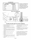
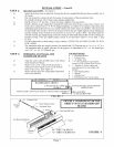
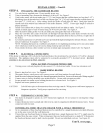
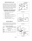
ROUGH INGAS SUPPLY- (See Figure 3)
Select the bottom, rear or right side to bring the t:actory supplied flexible gas line assembly out of
the heater.
The valve must be connected only by means of a pipe union of the ground joint type.
Mr. Installer, hold gas valve when connecting gas supply line.
Install at least a 3/8" gas line. Contact local gas supplier if any questions.
Install a drip leg in gas supply line immediately upstream from the gas connection to heater, (see
local codes), and provide a 1/8" N.P.T. plugged tapping, accessible for test gauge connection and a
individual manual shut off valve accessible within room where heater is installed. The heater and
its individual shut off valve must be disconnected t}om the gas supply piping system during any
pressure testing of that system at test pressures in excess of ½ psig (3.5Pa). The heater must be
isolated from the gas supply piping system by closing its individual manual shut off valve during any
pressure testing of the gas supply piping system at test pressures equal to or less than ½ psig
(3.SPa).
Test all connections for leaks using a soapy solution. NEVER USE AN OPEN FLAME TO TEST
FOR LEAKS.
The maximum inlet gas supply pressure for natural and L.P./Propane gas is V:p.s.i, or 14" w.c.
The minimum inlet as supply pressure for the purpose of adjustment is 4.5" w.c. for natural gas
and 11.0" w.c. for L.R/Propane gas.
STEP 3.
a)
b)
c)
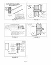
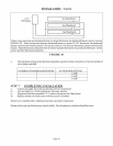
PREPARING TO INSTALL THE
BASEBOARD HEATER
Open the carton and carefully remove the Direct
Vent Baseboard Heater.
Remove the cover of the baseboard heater's
cabinet by removing the screws at the bottom
front of the cover. (See Figure 4.)
Make sure that all of the components illustrated
have been included.
YOU SHOULD HAVE:
,, 1 Baseboard Heater
,, 1 Exhaust Tube
• 1 Air Intake Tube
• 1 4" [10 cm] Stainless steel flexible
connector with a manual shut-off valve
• 1 Template to locate venting and
mounting positions (in package with
manual)
• 1 Vent Sealing Gasket
• 1 Manual
• 1 Weather Seal
• 1- Wall thermostat w/wire & staples
[72" :09_0,0 I
| 2 FROM END OF CABINE ? FLEX LINE BALL VALVEMUST BE
..| ABOVEFLOOR
MANUALStRJTOFFVALVEWITH 1/8 NPTPLUGGEDTAP "GAS SUPPLY
DRIPLEG-I 1/2"BLACKIRONPIPE
FIGURE 3
_v _ Exhaust Tube
Indoor Intake Gasket
Weather
Seat /_ Air Intake Tube
p Screws
FIGURE4: COMPONENTS OF THE
DIRECT VENT GAS BASEBOARD
HEATER
/_ Flex Line Ball Valve
Gas Baseboard Heater
/_ Screws
Cover
48 - BBT5_ & BBT54
_s 72"-BBT103 &BBT104
FIGURE 4
Page 7