


Version 2.0e 21
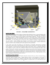
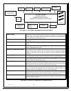
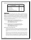
STOVE ELECTRICAL DIAGRAM
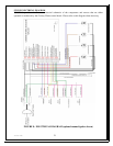
FIGURE 8 provides the Harvester electrical schematic of the components and sensors that are either
operated or monitored by the Country Flame control board. Please refer to this diagram when necessary.
FIGURE 8: ELECTRICAL DIAGRAM (optional manual igniter shown)