


Standard Mounting Kit
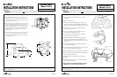
1. The standard mounting kit may be mounted to any
standard, embedded, 4" junction box. It is not for use
with a surface mounted J-box. For orientation of fixture
to the junction box (See Fig. 1).
2. Using the two (2) screws supplied with the junction box,
install the mounting plate as shown. The 5/16-18 studs
should be facing away from the wall and above the
center of the bracket (See Fig. 2). For rough or uneven
surfaces, sealant must be applied (by others) between
the rear mounting plate gasket and the mounting
surface (wall).
3. In addition to the screws supplied with the junction box,
the unit must be supported by 1/4" anchor screws
(supplied by others) installed through the four (4) holes
provided. (See Fig. 3).
These instructions do not claim to cover all details or variations in the equipment, procedure, or process described, nor to provide directions for meeting every possible
contingency during installation, operation or maintenance. When additional information is desired to satisfy a problem not covered sufficiently for user’s purpose, please
contact your nearest representative.
AVU033142
VISION WALL
Sheet 2 of 4
12/29/03 IMI-498
INSTALLATION INSTRUCTIONS
IMPORTANT: Read carefully before installing fixture. Retain for future reference.
TM
Fig. 3
Fig. 2
Fig. 1
WARNING: Make certain power is OFF
before starting installation or attempting any maintenance.
12 9/16”
(319.16mm)
4 11/16"
(118.6mm)
9 3/16”
(233.12mm)
3 1/2"
(88.9mm)
6 5/16”
(161.2mm)
These instructions do not claim to cover all details or variations in the equipment, procedure, or process described, nor to provide directions for meeting every possible
contingency during installation, operation or maintenance. When additional information is desired to satisfy a problem not covered sufficiently for user’s purpose, please
contact your nearest representative.
WARNING: Make certain power is OFF before starting installation or attempting any maintenance.
VISION WALL
Sheet 3 of 4
12/29/03 IMI-498
AVU033142
INSTALLATION INSTRUCTIONS
IMPORTANT: Read carefully before installing fixture. Retain for future reference.
TM
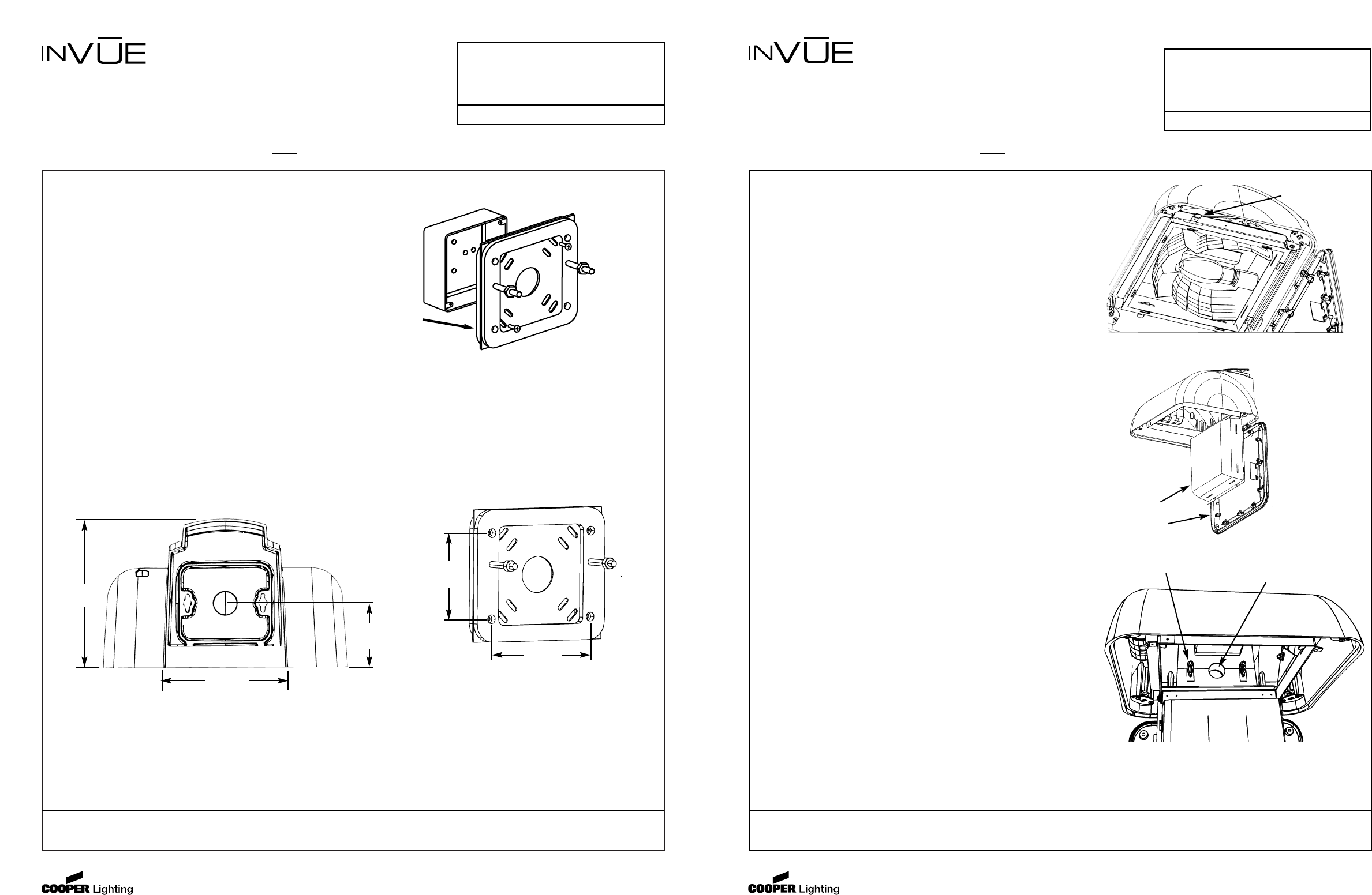
Installing the Fixture
1. You may install the fixture with the light up or down,
as desired.*
2. Make sure all power is off.
3. Visually inspect the mounting bracket to insure correct
placement and check for damaged gaskets (Refer to the
specific mounting instruction sheet used with your fixture.)
4. Loosen the four (4) 1/4-20 captive socket head cap
screws and open the door.
5. Locate two (2) reflector latches on either side of the
forward end of the reflector (See Fig. 1).
6. Turn the latches to disengage and pivot the reflector
assembly out of the way (See Fig. 2).
7. Thread the incoming power leads through the large
center hole in the rear of the fixture while lining up the
bolts (or threaded studs) with the keyhole slots in the rear.
(See Fig. 3)
8. Carefully slide the fixture down the keyhole, taking care
not to damage the gaskets.
9. Tighten the screws or nuts (Depending on mounting type).
DO NOT CAULK AROUND THE FIXTURE.
10. Have a qualified electrician make the power connections.
11. Push the supply wires back through the center hole and
down in the rear fixture cavity.
12. Swing the reflector assembly back up and latch into
position.
13. Install the door and four (4) 1/4-20 screws. Tighten the
screws diagonally opposed.
* When used with Thru-Way Mounting Box Accessory
VWM/TB, unit can only be mounted downward.
Fig. 1
Fig. 2
Fig. 3
Reflector
Door
Thread Power Feed Lines
Thru Here
Mounting Studs
Reflector Latch
Apply Sealant
As Required.
See Note #2.