


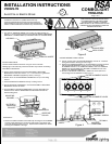

GIMBAL BRACKET
(Standard Position)
SLOT
SET SCREW
SNOOT
GIMBAL RING
GIMBAL
BLOCK
17. Once removed, flip the two (2) GIMBAL BRACKETs around (180°) and
tighten the joint if necessary. See Fig. 9.
If necessary, please see Step 21 for gimbal tightening instructions.
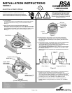
18. Reinsert the lamp ring assembly by turning it
counter-clockwise
into the
SLOTs on the GIMBAL BLOCKs. Re-tighten the two (2) SET SCREWs
in the GIMBAL BLOCKs. The lamp ring assy should now be oriented in
the "up position". See Fig. 10.
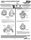
BAYONET
SLOTS
COVER
RING
PIN
BACK RING
COVER RING
(AS INSTALLED)
GIMBAL BRACKET
(Rotated 180° to
"Down" Position)
19. To replace the COVER RING:
Push the COVER RING onto the BACK RING by lining up the
BAYONET SLOTS (see Fig. 11) with the two (2) PINs in the BACK RING.
Figure 10
Figure 11
Figure 12
Figure 9
20. Once lined up, push straight back until the COVER RING stops, then
while keeping the COVER RING pushed back, turn
clockwise
until it
pushes forward again slightly. See Fig. 12.
21. Gimbal tightening instructions:
The lamp ring is intended to give positive tension at the PIVOT JOINTS
so the lamp ring can be aimed by hand and held in place by tension.
*If a stronger, more secure lock is required then the PIVOT JOINTS (hex
screws) may be tightened
clockwise
with a hex wrench tool. See Fig. 6.
*Please note that in some conditions the COVER RING will need to be
removed to gain access to the inner PIVOT JOINTS.
INSTALLATION INSTRUCTIONS
V90229-3
Avoid Fire or Electric Shock
COMBOLIGHT
LAMPHOLDER
Page 3 of 3
THIS PRODUCT MUST BE INSTALLED IN
ACCORDANCE WITH THE APPLICABLE
INSTALLATION CODE BY A PERSON
FAMILIAR WITH THE CONSTRUCTION AND
OPERATION OF THE PRODUCT AND THE
HAZARDS INVOLVED.
*Installation Instructions for qualified electricians only.
*Install per National Electrical Code and local regulations.
*Read Installation Instructions completely before installation.
*Failure to follow Installation Instructions may void warranties.
R