


STREETWORKS Outdoor Lighting Solutions 177Cooper Lighting
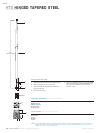
HINGED TAPERED STEEL POLES
Mounting Fixture No. & Accessories
Shaft
3
Wall Height Base Mounting Location Arm (Ground
Square Straight Steel Size Thickness (ft.) Type Finish & Type of Arms Lengths Lug)
HT S6 B 30 SPM 2 XG
Bolt Anchor
Base Circle Bolt Shaft Bolt Net. Max. Fixture
Mtg. Catalog
1, 2
Wall Square Dia. Proj. Size Dia. &. Wt. EPA (Sq. Ft.)
4
EPA (Sq. Ft.)
4
Load—Include
Height Number Thickness (In.) (In.) (In.) (In.) Length (In.) (Lbs.) At Pole Top 2' Above Pole TopBracket (Lbs.)
MH S BC BP B D x AB x H 80 90 100 80 90 100
20 HTS6A20SF .120 Consult your Cooper Lighting Representative
25 HTS6A25SF .120 Consult your Cooper Lighting Representative
30 HTS7A30SF .120 Consult your Cooper Lighting Representative
30 HTS7D30SF .188 Consult your Cooper Lighting Representative
35 HTS8A35SF .188 Consult your Cooper Lighting Representative
35 HTS8D35SF .188 Consult your Cooper Lighting Representative
39 HTS8A39SF .188 Consult your Cooper Lighting Representative
39 HTS8D39SF .188 Consult your Cooper Lighting Representative
NOTES: 1 Catalog number includes pole with anchor bolts with double nuts (BEFORE INSTALLING ANCHOR BOLTS MAKE SURE PROPER ANCHOR BOLT TEMPLATE IS OBTAINED FROM COOPER LIGHTING HEADQUARTERS).
2 Tenon size or machining for rectangular arms must be specified. Hand hole is located 180° from single arm.
3 Shaft size, base plate, anchor bolts and projections may vary slightly—all dimensions nominal.
4 EPAs based on shaft properties with wind normal to flat. EPAs calculated using base wind velocity as indicated plus 30% gust factor.
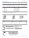
MACHINING FOR RECTANGULAR ARMS [Add as suffix]
Designation Designation Designation Quantity
Letter & Number Letter & Number Letter & Number & Location
M1 E1 Z1 Single
M2 E2 Z2 2 @ 180°
M3 E3 Z3 3 @ 120°
M4 E4 Z4 4 @ 90°
M5 E5 Z5 2 @ 90°
M6 E6 Z6 3 @ 90°
M7 E7 Z7 2 @ 120°
NOTES: Refer to Fixture Drilling Options on page 160.
ACCESSORIES
A=1/2" tapped hub
1
B=3/4" tapped hub
1
C=Convenience outlet
2
G=Grounding lug (max. wire #8 AWG)
H=Additional hand hole and cover—
12" below pole top—90° from hand hole.
NOTES: 1 Location is 3' above base–90° from hand hole.
2 Outlet is located 4' above base and on same side of pole
as hand hole, unless specified otherwise. Receptacle not
included, provision only.
MOUNTING OPTIONS [Add as suffix]
Fixed Tenon Designation O.D. Length
Number (In.) (In.)
1 2 3/8 3 1/2
2 2 3/8 4
3 3 1/2 5
934
7/8''
2 13/16''
3/4'' dia.
hole
(2) 3/8"
dia. holes
3 7/8''
DRILLING PATTERN
Type “M” [RCL, Landau, Galleria and Vision] Type “E” [Concourse III] Type “Z” [Credenza and Cirrus]
3/4'' dia.
hole
(2) 5/8''
dia. holes
2 7/16''
2 5/16''
4 7/8''
O.D.
LENGTH
LOWERING EQUIPMENT
Catalog Net. Wt.
Number Description (Lbs.)
HSSLDW Lowering Device 11.5
w/35' Cable and
Snap-hook
NOTES: Lowering Device No. HSS-LDW is required for use with all Cooper Lighting
hinged poles. This Device consist of a wench, arm, and a rotating steel drum
with a two-way ratchet lock and 35' of stranded flexible aircraft cable.
The drum has a gear ratio of 51 to 1. Combination arm, gear and lever
provide a mechanical advantage of 30 to 1 and permit a direct load lift of
up to 1300 lbs.
9/16" [14mm]
dia. hole (3)
4 7/8" [124mm]
4" [102mm]
2 7/16" [62mm]
ORDERING INFORMATION
SAMPLE NUMBER: HTS6B30SPM2XG
NOTE: Specifications and dimensions subject to change without notice.