MAINTENANCE INSTRUCTIONS
AIRFLOW ADJUSTMENT (Applicable for PT075 - PT360 only)
The airflow could be adjusted by adjusting pulleys of blower motor or belt tension with proper mounting and alignment of the pulleys:
• Refer to fan performance tables in the catalog for selecting applicable airflow, RPM and brake horse power at specified static
pressure.
• Select the appropriate drive as per motor and blower characteristic in the catalog.
• The set screw shall be loosened to make the pulley moving.
• Adjust pulley’s diameter, opening counter clockwise to reduce RPM and further reduce airflow, while closing clockwise increases
RPM and airflow.
• Tighten the set screw and then install the belts.
• Test the unit operating airflow for further adjustment.
CRANKCASE HEATER
• Periodic checking for proper operation or crankcase heater is highly recommended as follows:
a) Check continuity of the heater using multimeter device.
b) Check grounding of the heater by Meggar device (to prevent electrical hazards).
c) Observe whether the heater is warming down the compressor near the oil sump.
CLEANING OF COILS & FILTERS
• Turn off the power supply.
• Take out access panel of evaporator coil.
• Remove the filter from its access panel.
• Protect electrical components and motors from water washing.
• Clean the coil by flushing water by pressure washer followed by compressed air from supply to return direction.
• Filter shall be cleaned every six month, in some hygienic application it is recommended for replacement.
• Cleaning drain pan and trap is recommended once in a year to prevent bacteria growing under the coil.
BELT TENSION TESTING PROCEDURE INSTRUCTION (Applicable for PT075 - PT360 only)
To determine the lbs. force required to tension a drive, you simply do the following:
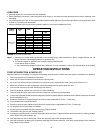
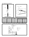
1. Measure the Belt span as shown.
2. Divide belt span by 64 to get belt deflection needed to check tension.
3. Set large "0" ring on span scale at required belt deflection. This scale is in 1/16" increments.
4. Set small "0" ring at zero on the "Force Scale" (plunger).
5. Place the larger end of the tension checker squarely on one belt at the center of the belt span. Apply force on the plunger until the
bottom of the large "0" ring is even with the top of the next belt or with the bottom of a straight edge laid across the sheaves.
6. Read the force scale under the small "0" ring to determine force required to give the needed deflection.
7. Compare the force scale reading with the correct value for the belt style and cross section used, as given in table on next page.
The force should be between the minimum and maximum values shown.
8. If there is too little deflection force, the belts should be tightened. If there is too much deflection force, the belts should be
loosened.
Note: Tension new drives at the maximum deflection force recommended. Check the tension at least two times during the first day's
operation as there normally will be a rapid decrease in belt tension until belts have run in. Check the tension periodically after the first
day's operation and keep tension in recommended area. The correct operating tension for a V-belt drive is the lowest tension at which
the belts will not slip under the peak load conditions. Shafts must be adequate for the tensions required.
17


