


7
Majestic Fireplaces® UVC / UVS Vent-Free Heaters
20000135
GF443 UVC
(from GF379)
2/11/97
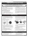
Parts Identification
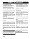
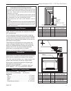
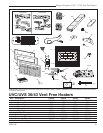
Fig. 6 Parts identification.
FP443
Catalytic Filters
(Behind Grille)
UVC
Top Louvre
Screen Panel (UVS)
Glass Panel (UVC)
Firebox
Bottom Louvre
(Bottom Access Door)
(Controls behind louvre)
Gas
Line
Access
Nailing
Flange
Logs and Burner
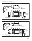
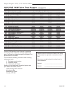
Gas Specifications
Max. Min.
Model Fuel Gas Control Input Input
B.T.U.H. B.T.U.H.
UVC36RN Natural Millivolt Hi/Lo 25,000 17,500
UVC36RP Propane Millivolt Hi/Lo 25,000 18,750
UVS36RN Natural Millivolt Hi/Lo 25,000 17,500
UVS36RP Propane Millivolt Hi/Lo 25,000 18,750
UVC43RN Natural Millivolt Hi/Lo 33,000 23,100
UVC43RP Propane Millivolt Hi/Lo 33,000 24,750
UVS43RN Natural Millivolt Hi/Lo 33,000 23,100
UVS43RP Propane Millivolt Hi/Lo 33,000 24,750
Natural LP
Minimum Inlet Pressure 5.5" w.c. 11.0" w.c.
Maximum Inlet Pressure 14.0" w.c. 14.0" w.c.
Manifold Pressure 3.5" w.c 10.0" w.c.
Gas Inlet and Manifold Pressures
UVC36 / UVS36 / UVC43 / UVS43
Certified To
ANSI Z 21.11.2a-2003
Unvented Room Heaters
Units: B42A00, B42B00, D42A00, D42B00, B41AS0,
B41BS0, D41AS0, D41BS0
High Elevations
Input ratings are shown in BTU per hour and are
certified without deration from elevations up to
4,500 feet (1,370m) above sea level.
Nuisance outages may occur at altitudes above
4,500 feet (1,370m) if dirt, dust, lint and/or cob-
webs are allowed to accumulate on burner and/or
ODS pilot. Monthly inspection and cleaning is
recommended for altitudes above 4,500 feet
(1,370m)
For elevations above 4,500 feet (1,370m), instal-
lations must be in accordance with the current
ANSI Z223.1/NFPA 54 and/or local codes having
jurisdiction.
The installation of your Majestic Fireplaces room-
heater must conform with local codes, or in the
absence of local codes, with National Fuel Gas
Code, ANSI Z223.1/NFPA 54 — latest edition. (EX-
CEPTION: Do not derate this appliance for altitude.
Maintain the manifold pressure at 3.5 inches w.c.
for Natural Gas and 10 inches w.c. for LP gas.)
Gas Supply Pressures
This heater must be isolated from the gas supply piping
system by closing its individual manual shut-off valve
during any pressure equal to or less than 1/2 psig (3.45
kPa).
The heater and its individual shut-off valve must be
disconnected from the gas supply piping system during
any pressure testing of that system at test pressures in
excess of 1/2 psig (3.45 kPa).
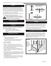
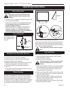
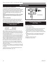
Connect the Gas Line
If gas piping from the source to the heater location has
not been accomplished, install the required pipe. Con-
sult local plumbing code to assure proper pipe size.
The gas pipeline can be brought in through the right or
left side of the heater, as well as the bottom. Knockouts
are provided at convenient locations to allow for the gas
pipe installation and testing of any gas connection. It is
most convenient to bring the gas line in from the right
side, as this allows fan installation or removal without
disconnecting the gas line.
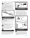
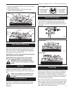
NOTE: The gas line connection can be made with
properly tinned 3/8" copper tubing, 1/2" rigid pipe or an
approved flex connector, then reduced to 3/8" to the
heater. Because some municipalities have some addi-
tional local codes, it is always best to consult your local
authority. Consult the current National Fuel Gas Code,
ANSI Z223.1/NFPA 54.