9
UVS27 Vent-Free Gas Heater
20007068
Assembly Procedures
CAUTION
Porcelain enamelled surfaces are fragile. Handle
porcelain enamelled castings tenderly. Familiarize
yourself with the assembly steps before you begin
and proceed with deliberation and care. If possible,
have assistance available.
Place enamelled castings on a soft, cushioned sur-
face until you are ready to assembly.
Avoid contact between the castings and other hard
surfaces or objects.
Unpack the Stove
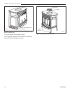
The UVS27 is shipped fully assembled on its back.
Unpack the stove and carefully set it upright.
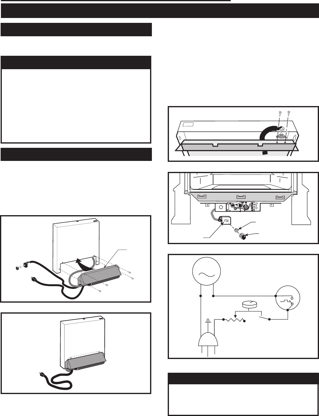
Install Optional Fan Kit
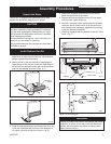
1. Remove shroud assembly by loosening two (2) hex
head bolts on lower inside of shroud. Lift shroud as-
sembly up and away from stove.
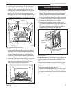
2. Attach the fan to the rear shroud by engaging the
upper flange of the fan skirt under the lower edge of
the shroud and secure the skirt with the four screws
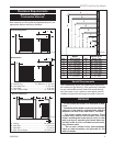
and one star washer provided. (Figs. 4, 5)
FK104
Install cover plate
Rheostat
Retaining Nut
Control Knob
FK104
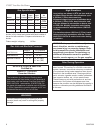
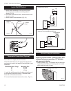
Fig. 7 Attach rheostat to bracket.
MOTOR
SNAPSTAT
ON/OFF
RHEOSTAT
WHT
WHT
BLK
BLK
BLK
GRN
BLK
ST236
FK26 wiring diagram
12/99
ST236
Fig. 8 Fan wiring diagram.
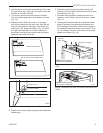
4. Secure the snapstat wire harness to the shroud
panel using the wire tie provided.
5. Replace shroud and tighten the two (2) hex head
nuts on lower inside of shroud.
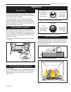
6. Route the rheostat control switch and wire forward
under the stove. Use the wire tie to secure the fan
and rheostat wire harnesses together to the tubing
under the bottom heat shield.
7. Install the rheostat onto the bracket to the left of the
valve. (Fig. 7)
ST344a
pinnacle
install fan
2/4/00
Upper
Flange
ST344a
Fig. 4 Place upper flange behind lower edge of shroud.
ST345a
Fig. 5 Correct position of fan skirt installation.
ST345a
pinnacle
fan in place
12/18/03
ST346a
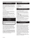
Fig. 6 Attach snapstat to inner shroud.
ST346a
install FK28
snapstat
12/18/03
3.
Feed the snapstat wire lead up between the inner and
outer rear shroud panels and secure the snapstat to
the upper right side of the inner shroud. (Fig. 6)
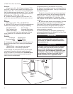
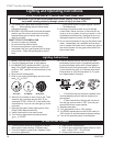
WARNING
Failure to position the parts in accordance with these
diagrams, or failure to use only parts specifically ap-
proved with this heater may result in property dam-
age or personal injury.


