


1120008056
Gas Connection
Check Gas Type. Use only the gas type indicated on the
heater’s rating plate. If the gas type indicated on the plate is
not your type of gas supply, DO NOT INSTALL. Contact your
dealer for the proper model.
WARNING
DANGER OF PROPERTY DAMAGE,
BODILY INJURY OR DEATH.
Make sure the heater is equipped to operate on
the type of gas available. Models designated as
natural gas are to be used with natural gas only.
Heaters designated for use with liquefied petro-
leum (l.p.) gas have orifices sized for commercial-
ly pure propane gas. They cannot be used with
butane or a mixture of butane and propane.
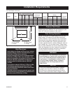
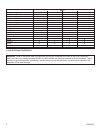
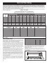
Gas Piping. The gas supply line must be of an adequate size
to handle the BTU/HR requirements and length of the run for
the unit being installed.
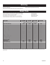
Determine the minimum pipe size from the piping size chart on
Page 12. The normal gas connection at this appliance is 1/2”
NPT made at the left of the unit.
Always use an external regulator for all LP installations to reduce
the supply tank pressure to a maximum of 13” w.c. This is in ad
-
dition to the regulator fitted to the heater.
All piping must comply with local codes and ordinances or with
the National Fuel Gas Code (ANSI Z223.1/NFPA 54), whichever
applies.
WARNING: Connecting directly to an unregulated
LP tank can cause an explosion.
Gas Connection. If installation is for L.P. gas, have L.P. in-
staller use two-stage regulation and make all connections from
storage tank to heater. Refer to the National Fuel Gas Code for
the proper supply tank size with the Btu’s/Hr requirements. If
this is the ONLY gas appliance, we recommend a minimum 200
pound cylinder with a fill gauge. Use of a 100 pound cylinder
is not recommended. Other household gas appliances may
require the tank size to be larger.
Use two pipe wrenches when making the connection to the
valve to prevent turning or damage to gas valve or regulator.
Connection between the manual shut-off valve and the gas
valve can be made with a CSA design certified flexible connec
-
tor if allowed by local codes. A 10 inch, 1/2” NPT listed stain-
less steel flexible connector is supplied with the gas log heater.
Tighten all joints securely.
CAUTION: Failure to install a drip leg (sediment trap)
may result in improper combustion that will produce soot.
Reference Sections 3.7 and 5.5.7 and Figure 5.5.7 of the
National Fuel Gas Code for guidance.
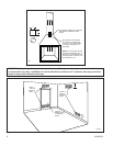
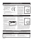
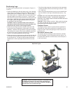
Typical Gas Line Connection
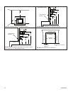
Step 1: With the engine assembly free from the fireplace, check
tightness of flexible connector fittings.
CAUTION: Use one wrench to hold the valve and one
wrench to loosen and tighten the brass adapter and the flex
line connection. Failure to hold the valve while loosening
and tightening the fittings can damage the unit and cause
gas leaks.
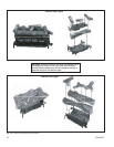
Step 2: Set the engine assembly into the fireplace and connect
the flexible connector to the gas piping that has been installed
per local codes, or in the absence of local codes, ANSI Z223.1/
NFPA 54 latest edition.
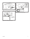
Step 3: After the last connection is made, screw the engine as
-
sembly to the bottom of the fireplace. (Fig. 3)
Step 4: Test all connections on the unit and piping for gas
leaks.
Testing the Gas Piping. Test all piping for leaks. When check
-
ing gas piping to the heater with gas pressure less than 1/2
PSI, shut off manual gas valve for the heater. If gas piping is to
be checked with the pressure at or above 1/2 PSI, the heater
and manual shut off valve must be disconnected during testing
to prevent damage to the regulator on the unit, (see warning
below).
WARNING
DANGER OF PROPERTY DAMAGE,
BODILY INJURY OR DEATH.
Never use a match or open flame to test for leaks. Never
exceed specified pressures for testing. High pressures
may damage the appliance regulator which would re-
quire replacement. Liquefied petroleum (L.P.) is heavier
than air and it will settle in any low area, including open
depressions and it will remain there unless area is ven-
tilatedNever attempt start-up of unit before thoroughly
ventilating area.A.
WARNING: Be sure that the gas type indicated on the
gas log rating plate concurs with the gas system in your
building.
To ensure that the gas lines and connections do not have any
leaks, a pressure test should be performed. Only a qualified
installer should perform the pressure test to ensure that
the unit is not damaged by high pressures!
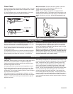
If you connect natural gas to an LP gas unit, you may be un-
able to ignite the pilot. If the pilot does ignite, the front burner
flame on the low setting will be bright blue but only 1/4” to 1/2”
long and most likely lifting off the burner ports. If this is the
case, turn the unit off immediately and contact the dealer where
the unit was purchased.
If you connect LP gas to a natural gas unit, the front burner
flame on the low setting will be about 6” - 8” long. On the
medium and high setting, the front burner flames will be bright
yellow and about 10” in length. Turn the unit off immediately! If
the unit is allowed to run in this condition, substantial amounts
of soot will be generated and emitted into the house. Contact
the dealer where the unit was purchased.