


9
20008055
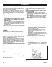
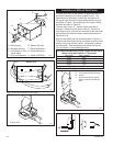
Installation of WRST or WRD Wireless Remote
To begin installation of your wireless remote (WRD or WRST),
you must first remove the two screws retaining the cover for the
ignitor/receiver delete plate as shown on the log set in Figure 5,
letter “E”. This allows the removal of the delete plate blocking
the holes for the receiver. Your receiver will be similar to that
shown in Figure 6, letter “G”.
There will be a battery terminal and two wire leads. Install the
receiver as shown in Figure 6 by attaching the two silver push-
on clips over the mounting ears as shown in Figure 6, letter “D”.
Line up the receiver as shown in the same diagram and push
the receiver up flush to the plate. The switch and pickup will
protrude from the front of the mounting plate.
Using the screws removed from the delete plate removal,
tighten the receiver to the plate. Now turn the whole log set
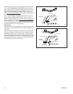
upside down and refer to Figure 7.
Run the red and white wires, letter “C”, from the receiver to the
valve as shown in Figure 7. The wires should now be in front of
the valve’s terminal shown in Figure 8. The two wires, letter “A”,
Figure 8, should not be removed or changed. Remove switch
wires, letter “B”. The two wires from the receiver can now be
connected to the two outer terminals on the valve, making sure
it is the two outer terminals and not the center one (see Figure
9). With these two connections made, return the log set right
side up. You may now refer to the lighting instructions for use.
The log set should not be modified to accept any other type
of remote control and no guarantee may be made regarding
proper function.
T109
wireless remote
10/27/03 djt
D
C
E
F
B
A
A Manual OFF/ON D Log
Switch E Receiver and battery
B Piezo Ignitor installation and removal screws
C Receiver F Switch (OFF/ON)
Fig. 5 Wireless remote installation.
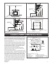
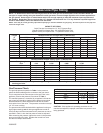
T109
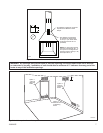
42"
16"
T105
Minimum
clearance to
walls & ceiling
10/27/03 djt
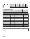
Fig. 4A Minimum clearance to wall and ceiling.
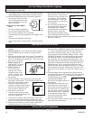
10"
8"
6"
1¹⁄₈"
10"
Min.
15"
Min.
19"
Min.
23"
Min.
27"
Min.
T106
Mantel clearance
no canopy
10/27/03 djt
Heat Resistant
Material
No Canopy Used
Fig. 4B Mantel clearances for existing fireplaces.
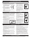
Fireplace Opening
10"
8"
6"
1¹⁄₈"
8"
Min.
T107
Mantel clearance
with canopy
10/27/03 djt
12"
Min.
16"
Min.
20"
Min.
Heat Resistant
Material
Fig. 4C Mantel clearance with Optional Universal Canopy,
UC-2 (black) or UC-2PB (polished brass).
Fireplace Opening
Universal
Canopy
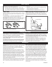
T107
side clearance
and projection
10/27/03 djt
Fireplace
Opening
Maximum Projection:
7”
2” Minimum
Clearance
Mantel Leg
Combustible Mantel
Noncombustible
Facing
Mantel Leg
Fig. 4D Side clearances and projection.