4
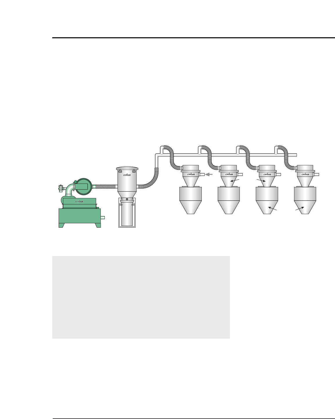
Set or mount the vacuum pump in any convenient location.
Refer to the accompanying wiring diagram for connection of
the main power supply and the conveying control circuit.You
must provide a wall-mounted disconnect for three-phase elec-
trical connection. Incoming voltage and current must match
the electrical specifications on the pump data plate and serial
tag. Check for proper rotation of the pump after power has
been connected and before operation.
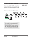
Install vacuum lines to loader stations and the dust collector.
Connect the dust collector vacuum outlet to the pump inlet.
INSTALLATION AND OPERATION NOTE:
The pump inlet is equipped with a vacuum relief
valve to prevent the vacuum from exceeding 12 in.
Hg. Excessive vacuum will reduce the life of the
pump and can destroy it.
For special applications requiring a higher vacuum
level, consult Conair service. If the vacuum relief
valve is adjusted by any person other than a facto-
ry service representative, the warranty is voided.
INSTALLING
THE
PUMP
IMB036/0898 Positive Displacement Pump
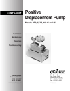
Positive
Displacement
Vacuum Pump
Central
Vacuum Line
Material
Inlet
Material
Receivers
Receiving
Hoppers
Central Dust Collector


