


18
103425
UNVENTED (VENT-FREE) GAS LOG HEATER
CLEANING AND
MAINTENANCE
WARNING: Turn off heater
and let cool before cleaning.
CAUTION: You must keep
control areas, burners, and cir-
culating air passageways of
heater clean. Inspect these areas
of heater before each use. Have
heater inspected yearly by a quali-
fied service person. Heater may
need more frequent cleaning due
to excessive lint from carpeting,
bedding material, pet hair, etc.
LOGS
• If you remove logs for cleaning, refer to
Installing Logs, page 14, to properly re-
place logs.
• Replace log(s) if broken or chipped
(dime-sized or larger).
WARNING: If yellow tipping
occurs, your heater could pro-
duce increased levels of carbon
monoxide. If front burner flame
pattern shows yellow tipping, fol-
low instructions at bottom of this
page. Yellow flame on rear burner
is normal.
FRONT BURNER FLAME
PATTERN
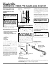
Figure 27 shows correct front burner flame
pattern. Figure 28 shows incorrect front
burner flame pattern. The incorrect burner
flame pattern shows yellow tipping at top of
blue flame.
If front burner flame pattern is incorrect, as
shown in Figure 28
• turn heater off (see To Turn Off Gas to
Appliance, page 16 [Thermostat-Con-
trolled Models] or page 17 [Variable
Manually-Controlled Models])
• see Troubleshooting, pages 19 through 21
NOTICE: Do not mistake orange
flames with yellow tipping. Dirt
or other fine particles are burned
by heater, causing brief patches
of orange flame.
Figure 28 - Incorrect Front Burner Flame
Pattern
Figure 27 - Correct Front Burner Flame
Pattern
Yellow Tipping At
Top of Blue Flame
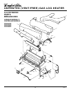
INSPECTING
BURNERS
Continued
CLEANING BURNER
INJECTOR HOLDER AND
PILOT AIR INLET HOLE
The primary air inlet holes allow the proper
amount of air to mix with the gas. This
provides a clean burning flame. Keep these
holes clear of dust, dirt, and lint. Clean these
air inlet holes prior to each heating season.
Blocked air holes will create soot. We rec-
ommend that you clean the unit every 2,500
hours of operation or every three months.
We also recommend that you keep the burner
tube and pilot assembly clean and free of
dust and dirt. To clean these parts we recom-
mend using compressed air no greater than
30 PSI. Your local computer store, hard-
ware store, or home center may carry com-
pressed air in a can. You can use a vacuum
cleaner in the blow position. If using com-
pressed air in a can, please follow the direc-
tions on the can. If you don't follow direc-
tions on the can, you could damage the pilot
assembly.
1. Shut off the unit, including the pilot.
Allow the unit to cool for at least thirty
minutes.
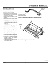
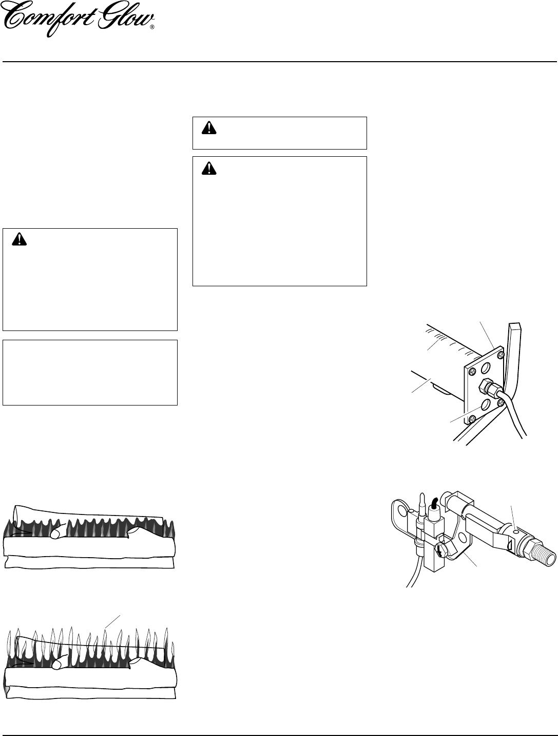
2. Inspect burner, pilot, and primary air
inlet holes on injector holder for dust
and dirt (see Figure 29).
3. Blow air through the ports/slots and
holes in the burner.
Figure 29 - Injector Holder On Outlet
Burner Tube
4. Check the injector holder located at the
end of the burner tube again. Remove
any large particles of dust, dirt, lint, or
pet hairs with a soft cloth or vacuum
cleaner nozzle.
5. Blow air into the primary air holes on
the injector holder.
6. In case any large clumps of dust have
now been pushed into the burner repeat
steps 3 and 4.
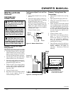
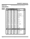
Clean the pilot assembly also. A yellow tip
on the pilot flame indicates dust and dirt in
the pilot assembly. There is a small pilot air
inlet hole about two inches from where the
pilot flame comes out of the pilot assembly
(see Figure 30). With the unit off, lightly
blow air through the air inlet hole. You may
blow through a drinking straw if compressed
air is not available.
Burner
Tube
Injector Holder
Primary Air Inlet
Holes
Figure 30 - Pilot Inlet Air Hole
Pilot Assembly
Pilot Air Inlet
Hole
Ports/Slots