


445349-CTG-B-0409
2 Johnson Controls Unitary Products
Nominal external static pressure is 0.50” w.c. at furnace outlet ahead of cooling coils.
Annual Fuel Utilization Efficiency (AFUE) numbers are determined in accordance with DOE Test procedures.
Wire size and over current protection must comply with the National Electrical Code (NFPA-70-latest edition) and all local codes.
HORIZONTAL SIDEWALL VENTING
For applications where vertical venting is not possible, the
only approved method of horizontal venting is the use of an
auxiliary power vent. Auxilary power venters must be
approved by CSA, UL, or other recognized safety agencies.
Follow all application and installation details provided by the
manufacturer of the power vent.
FILTER PERFORMANCE
The airflow capacity data published in the “Blower Perfor-
mance” table listed above represents blower performance
WITHOUT filters.
All applications of these furnaces require the use of field
installed air filters. All filter media and mounting hardware or
provisions must be field installed external to the furnace cabi-
net. DO NOT attempt to install any filters inside the furnace.
NOTE: Single side return above 1800 CFM is approved as
long as the filter velocity does not exceed filter manufac-
turer’s recommendation and a transition is used to allow use
of a 20x25 filter.
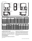
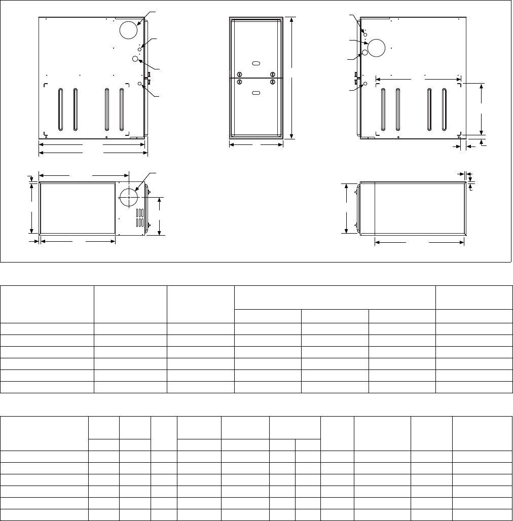
LEFT SIDE
RIGHT SIDE
.5”
.5”
RETURN END
B
24.25”
29.5”
28.5”
Electrical
Entry
Gas Pipe
Entry
Thermostat
Wiring
FRONT
14”
1”
1.5”
23”
SUPPLY END
C
24.38”
20”
.5”
B
Gas Pipe
Entry
Thermostat
Wiring
33”
A
.5”
Electrical
Entry
Vent Connection
Outlet
Vent
Connection
Outlet
4” Diameter
Outlet
Vent Connection
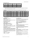
Cabinet and Duct Dimensions
Models
Nominal
CFM (m
3
/min)
Cabinet
Size
Cabinet Dimensions (Inches)
Approximate
Operating Weights
ABCLbs
TM(8,L)X060A12MP11 1200 A 14 1/2 13 3/8 10.3 94
TM(8,L)X080B12MP11 1200 B 17 1/2 16 3/8 11.8 103
TM(8,L)X080C16MP11 1600 C 21 19 7/8 13.6 114
TM(8,L)X100C16MP11 1600 C 21 19 7/8 13.6 118
TM(8,L)X100C20MP11 2000 C 21 19 7/8 13.6 122
TM(8,L)X120C20MP11 2000 C 21 19 7/8 15.8 129
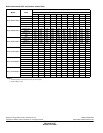
Ratings & Physical / Electrical Data
Models
Input Output
AFUE
Air Temp.
Rise
Max. Outlet
Air Temp
Blower
Blower
Size
Max
Over-Current
Protect
Total Unit
Amps
Min. wire Size
(awg) @ 75 ft
one way
MBH MBH °F °F HP Amps
TM(8,L)X060A12MP11 60 48 80.0 30-60 160 1/2 6.8 11 x 8 15 9.3 14
TM(8,L)X080B12MP11 80 64 80.0 35-65 165 1/2 6.8 11 x 8 15 9.3 14
TM(8,L)X080C16MP11 80 64 80.0 25-55 155 1/2 6.8 11 x 10 15 9.3 14
TM(8,L)X100C16MP11 100 80 80.0 35-65 165 1/2 6.8 11 x 10 15 9.3 14
TM(8,L)X100C20MP11 100 80 80.0 25-55 155 3/4 8.4 11 x 11 15 10.9 14
TM(8,L)X120C20MP11 120 96 80.0 35-65 165 3/4 8.4 11 x 11 15 10.9 14