


1347 HEIL QUAKER BLVD., LAVERGNE, TN 37086
Phone: (615) 793-3900 www.chromalox.com
MOUNTING AND WIRING
WARNING: Hazard of Electrical Shock. Disconnect
all power before wiring or servicing this control.
1. Electric wiring to heater must be installed in accordance with
Local and National Electrical Codes.
WARNING: Use copper conductors only.
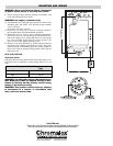
2. Pull thermostat wires through large opening in center of wall
mounting plate and fasten wires beneath proper terminal
screws as follows:
A. Connect to 4 and 5 as shown.
3. Push excess wire into wall or switch box and plug up hole to
prevent drafts from affecting thermostat operations.
4. Thermostat must be level to assure optimum performance.
Place level on top of wall mounting plate and mark hole loca-
tions for mounting screws. Attach plate loosely to wall with the
two screws provided. Again, place level on top of plate to be
sure it is level. Then, tighten mounting screws.
5. Remove cover from thermostat by pulling outward. Remove
and discard pad (shipping protection for switch). Place ther-
mostat base onto wall mounting plate and securely tighten all
three screws (four for heating-cooling models). Then, snap on
thermostat cover.
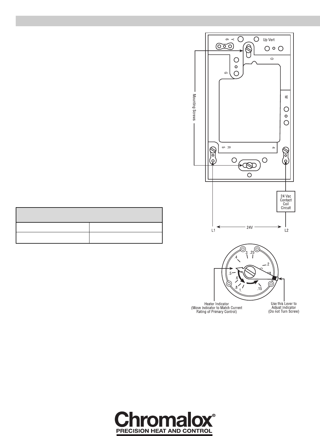
HEAT ANTICIPATION
Adjustable Heater
Set heater indicator to match the current rating of the primary con-
trol. Heater may be adjusted for current ratings from 0.15 to 1.0
Amp.
WARNING: The adjustable Heater (Heat Anticipator)
WILL BURN OUT if 25V are applied directly to ther-
mostat by shorting out the primary control during
testing or by incorrect wiring.
WARNING: This product contains mercury. Dispose
of thermostat in a manner in accordance with
local, state and federal laws.
Primary Control Circuit Ratings
60Hz
LUH 0.375A
KUH 0.375A
Longer
Limited Warranty:
Please refer to the Chromalox limited warranty applicable to this product at
http://www.chromalox.com/customer-service/policies/termsofsale.aspx.