


1347 HEIL QUAKER BLVD., LAVERGNE, TN 37086
Phone: (615) 793-3900 www.chromalox.com
WARNING: Hazard of Electric Shock. Extreme care
should be exercised during calibration adjustments
because of shock hazard due to exposed electrical
terminals.
DANGER: Calibration will involve exposure of inter-
nal control terminals to ambient conditions during
some part of the recalibration procedure.
Combustible materials which cause hazardous
conditions must not be present during recalibra-
tion process – otherwise explosion may result.
WR-80EP thermostats are accurately calibrated at the factory
so the dial setting correctly indicates the temperature at which the
contacts open on temperature rise. If, as a result of damage in tran-
sit or for other reasons the room temperature differs appreciably
from the dial setting, the calibration may be adjusted as follows:
1. Note temperature on the thermometer.
2. Set dial at highest temperature.
3. Turn dial slowly to lower temperature and stop when thermo-
stat contacts open.
4. Remove cover using the
3
/16” Allen Head Wrench as in #1
wiring.
5. Loosen two dial screws (Figure 2). Carefully turn the dial only
to correct temperature setting as indicated by thermometer. Be
sure the thermostat shaft is not moved during this operation.
6. Tighten the dial screws and replace thermostat cover. (See
“Replacing Cover”)
CALIBRATION
Ground
WIRING
WARNING: Hazard of Electric Shock. Disconnect all
power before wiring or servicing this control.
1. After a suitable location has been chosen for the control,
remove the front cover by using a
3
/16” Allen Head Wrench,
(furnished with control) in the 6 cover screws.
2. Electric wiring to heater must be installed in accordance with
National Electrical Code and with local codes. WARNING:
Use copper conductors only.
3. Entrance for wiring is provided by one
1
/2-14 NPT hole in the
bottom of the housing. Wiring to control housing must be in
rigid conduit also in accordance with National Electrical Codes
(NEC) for hazardous locations. (See Figure 2)
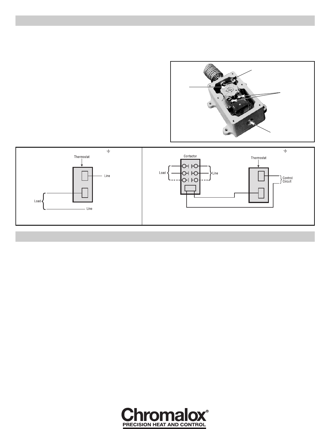
4. Connect wires according to wiring diagrams (Figures 3 and 4).
Note: Electrical connections should be made with generous
loops of wire – approximately 6” per lead.
Note: If load amperage or voltage rating exceeds switch rating,
a contactor must be used. Contactor and wiring to be supplied
by customer. (See Figure 4)
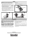
Replacing Cover
1. Set the internal dial and the external dial to the same setting so
that the hole in the dial lines up with pin on the arm that is
operated by the knob. (See Figure 2)
2. Replace 6 cover screws and tighten with Allen Wrench provided.
Ground
Figure 2
Figure 3 — Single phase loads when load does not exceed
rating of thermostat.
Figure 4 — Single phase loads when load exceeds rating of thermostat and three
phase loads.
Ground
Fixed
Indicator
1
/2-14
N.P.T. Thread
Electrical
Connections
Limited Warranty:
Please refer to the Chromalox limited warranty applicable to this product at
http://www.chromalox.com/customer-service/policies/termsofsale.aspx.